Laser Key Products 3D Pro Xtreme Скачать руководство пользователя страница 27

Page 

26

 of 

55


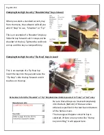
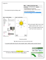
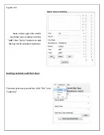
Then select the key blank being used. 


After placing the tubular key in the 

tubular jaw then click ‘Trace’ or 

enter cuts using the keyboard and 

click ‘Start’ when ready to cut. 
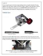
 

Tubular Key DSDs 

405, 406, 410, 411, 412, 413, 414, 415, 416 

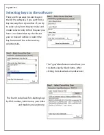
To search by DSD click ‘Search’ at the top left, enter a DSD number and click ‘Search’ 


The Tubular Jaw is supported by v5.38.8 or higher (v15 or above) 

To check your software version go to ‘Help > About’


Содержание 3D Pro Xtreme

Страница 1: ... will only operate as instructed on clean power Please make sure that the correct cutter and jaw combination are in place before cutting the key It is recommended that Safety Glasses be worn at all times when operating this machine ...

Страница 2: ...R 9 CALIBRATING THE 3D PRO XTREME 11 USING JAW 1 16 USING JAW 3 18 USING JAW 2 18 USING THE STANDARD TRACING ADAPTER 21 TROUBLESHOOTING THE STANDARD TRACING ADAPTER 23 TUBULAR JAW 24 TIBBE KEY AND TIBBE ADAPTOR 27 SELECTING KEYS IN THE SOFTWARE 30 SAVING AND LOADING CUSTOMER KEYS DATABASE 31 SPACE AND DEPTH ADJUSTMENTS 35 EXPLAINING THE SOFTWARE BUTTONS AND MENUS 42 KEY EDITOR 45 TROUBLESHOOTING 4...

Страница 3: ...o Xtreme key machines have a hard wired motor control cable but on older machines the 9 pin serial cable exiting the left side of the machine case should only be plugged into the 9 pin serial plug on the left side of the X table see pics below Be sure to tighten down the two small flathead attaching screws Do not plug the 9 pin serial cable into a computer this will short out the control board Com...

Страница 4: ...t side of the main home page under Popular Downloads click 3D Xtreme Software 2 Next to v15 Click Purchase and Download Now then click Add to Cart then click Checkout then provide Company and other information and click Submit the Information and in the Discount Coupon box use the coupon code provided in the white envelope received with new machines and select Use Coupon payment method and click C...

Страница 5: ...ll be instructed to email us your site code and wait for a site key Site codes are released Monday through Friday 9am 5pm Central Standard Time 2 If in the activation window Electronic registration or Email Registration Request doesn t work then copy and paste the site code to your webmail such as Gmail Yahoo or Hotmail and wait for a site key to be sent back to you then copy and paste the site ke...

Страница 6: ...rdware Wizard will appear Click install from specific location and Browse to c laser key products 3d pro windows drivers and click next and finish If an unsigned driver warning appears then select Continue Anyway 4 If the Found New Hardware Wizard didn t appear then open the Device Manager from the desktop icon labeled Device Manager and look for Other Devices Motion Controller Right Click Motion ...

Страница 7: ...operties 2 Under Port Settings change the Bits per second to 57600 3 Click the Advanced button and set the COM number to 2 and press OK and OK again on the Properties page and exit the Device Manager 4 Close the Device Manager window then push in the red button on the left side on the machine and unplug the USB cable going to the computer from the machine wait 30 seconds then twist the red button ...

Страница 8: ...is plugged into a USB port on your computer 4 Multiple instances of the 3D Pro software may be running causing a conflict check this by opening Task Manager Control Alt Delete on your keyboard and then clicking start Task Manager Select any items labeled 3D Pro Xtreme exe and then click End Process 5 Unplug the USB Cable for 15 seconds plug it back in and wait 15 more seconds and then start the so...

Страница 9: ...spindle stop button on the front of the head unit Now turn the knob on top with your hand until you feel the spindle stop button press all the way in Turn the knob counter clockwise and you will feel the collet loosen The cutter or stylus can now be removed Machines that do not have the spindle stop button will have a red knurl knob underneath the head unit that you will use together with the top ...

Страница 10: ...chine to recalculate the cutting path Changing Tracer When changing the tracer tighten the set screw that holds the tracer tip in place in between the two dimples The tracing function for duplicating keys works only on metal don t try to duplicate plastic keys Single ended tracer tip installation 1 Loosen Set Screw on tracer Swing Arm and remove current tracer 2 Install the Tracer into the Tracer ...

Страница 11: ...igh Security keys and the Jaw 2 is for standard security keys When changing a jaw look behind where the jaw is attached you will notice a red T knob Turn the T knob counter clockwise to release the lock pin the jaw can be now be removed from the table by sliding it off to the right Replacing the jaw is the same operation in reverse order if the jaw will not slide into place make sure the angle of ...

Страница 12: ...ibrate or else your keys will cut wrong This is the Stylus 3 Make sure the tracer arm is up if the tracer arm is down you will receive an error message 6 On the main screen click on the Operations menu and choose Calibrate Machine 5 When the window appears asking to Select Jaw insert the correct jaw number in the window 1 1 2 or 3 depending on which jaw you want to calibrate as we are calibrating ...

Страница 13: ...on the Operations menu and choose Calibrate Tracer 4 When the window appears asking to Select Jaw insert the correct jaw number in the window 1 2 or 3 depending on which jaw you want to calibrate as we are calibrating Jaw 1 we would enter 1 and click OK 5 The tracer tip will touch the jaw in three places After the procedure is complete it will read Update in Progress Please Wait give it a moment a...

Страница 14: ...ct Jaw insert the correct jaw number in the window 1 2 or 3 depending on which jaw you want to calibrate as we are calibrating Jaw 2 we would enter 2 and click OK 6 The cutter wheel touches the front of the A side of the Jaw 2 and then moves to the left and touches the shoulder stop then goes home After the procedure is complete it will read Update in Progress Please Wait give it a moment and don ...

Страница 15: ...m is up if the tracer arm is down you will receive an error message 4 On the main screen click on the Operations menu and choose Calibrate Machine 5 When the window appears asking to Select Jaw insert the correct jaw number in the window 1 1 2 or 3 depending on which jaw you want to calibrate as we are calibrating Jaw 3 we would enter 3 and click OK 6 The stylus will touch the jaw in three places ...

Страница 16: ...lick on the Operations menu and choose Calibrate Tracer 4 When the window appears asking to Select Jaw insert the correct jaw number in the window 1 2 or 3 depending on which jaw you want to calibrate as we are calibrating Jaw 3 we would enter 3 and click OK 5 The tracer tip will touch the jaw in three places After the procedure is complete it will read Update in Progress Please Wait give it a mom...

Страница 17: ... selecting the key look under the Step 2 column on the home screen you will find the tip stop number next Stop under the cutter image It will read Tip 1 Tip 2 or Tip 3 Place the tip stop in the correct slot lay the key flat in the jaw and slide the key forward until it touches the tip stop then tighten the jaw using the red knob on the right side of the Jaw 1 and then remove the tipstop Warning Do...

Страница 18: ...t forward until the shoulder of the key is touching the front of the jaw Tighten the red knob to lock the key in place Jaw 1 B Side When a Mercedes 2 Track or BMW HU92 2 Track key is selected it requires that the Jaw 1 B side be used Open the Jaw 1 and slide the movable side of the Jaw 1 top off the Jaw 1 and slide it back on with the B side on the left ...

Страница 19: ... JAW 2 When loosening the Jaw 2 clamp be careful not to unscrew the red T knob too far doing will cause the moving Jaw 2 top to slide out of the fixed Jaw 2 inner base and will require special instructions to reassemble Changing Jaw 2 Clamp To change which jaw clamp faces the cutting wheel all you have to do is loosen the jaw 2 and firmly twist the jaw 2 in any direction until the desired jaw clam...

Страница 20: ...y Clamping Non High Security Tip Stop Keys in Jaw 2 This is an example of a Tip Stop key Insert the key into the jaw and raise the Tip Stop slide the key forward until it touches on the stop Remember to fold the Shoulder or Tip Stop back down before you start to Trace or Cut a key Be sure that all keys are inserted completely into the back bottom of the Jaw unless otherwise specified in the text b...

Страница 21: ... key tight as illustrated In the example to the right we are using a hex wrench to shim the key Cut Types Slotted Cuts are not available at this time Laser Cut Plunge Cut Double sided keys will not automatically align in the Jaw 2 if there is no 1 depth toward the tip of the key To keep the key correctly aligned in the jaw you must align the key by eye The best way to do this is to line up the mil...

Страница 22: ...w 1 where a high security key would clamp When clamping Standard Security keys in the Standard Security Adapter it doesn t matter if you clamp on the milling or on the top of the key The machine detects how the key is clamped and traces accordingly Clamp whichever way works best Clamping Shoulder Stop Keys Press down on the red knob to open the key clamp This is an example of how to clamp a double...

Страница 23: ...lamping Incorrect Clamping Initiating a trace from the software After the key is clamped select the key to be duplicated in the 3D Pro software and click Single Trace or Double Trace Single trace will work for most keys most of the time but Trace Double can be more accurate by getting parameters from a blank software will ask you to insert a key blank first trace the blank and then trace the cut k...

Страница 24: ...dle column for Jaw 2 and find the Tracer section under the Cutter section Jaw 2 Tracer settings must match Jaw 1 Tracer settings for X Y and Z Start If not then copy the Jaw 1 Tracer settings to the Jaw 2 Tracer settings for X Y and Z Start Check that your settings for Jaw 2 Tracer match those in the above image for Calibration X1 600 Calibration Y1 60 Calibration X2 400 Calibration Y2 800 Make an...

Страница 25: ...e Standard Tracing Adapter be completely flat on Jaw 1 Tubular Jaw Tubular Cutter Cutter 4 Tubular Tracer Make sure the single ended tubular tracer is installed into the Tracer Swing Arm just under where the mark was made to where the tracer tip is just under half an inch sticking out of the swing arm Insert the Tubular Cutter After installing the Tubular Tracer CALIBRATE THE TUBULAR TRACER ON JAW...

Страница 26: ...sembly slide off the main jaw assembly and slide on the Tubular Jaw There is a spacer on the left side of the Tubular Jaw that stops on the silver screw Tighten the red t knob to lock the Tubular Jaw into place Supported Blanks ILCO 1137B LSDA 1137B JMA CHI 1T Clamp keys in the jaw with the notch of the key placed into the cut out at the back of the jaw Tighten the red knob on the front until the ...

Страница 27: ...ce or enter cuts using the keyboard and click Start when ready to cut Tubular Key DSDs 405 406 410 411 412 413 414 415 416 To search by DSD click Search at the top left enter a DSD number and click Search The Tubular Jaw is supported by v5 38 8 or higher v15 or above To check your software version go to Help About ...

Страница 28: ...Page 27 of 55 Tibbe Key and Tibbe Adaptor This enables us to insert the key blank into the adaptor sideways and rotate 90 into place Cutting a FORD Tibbe Key Silca FO21 DSD 358 ...

Страница 29: ...21 DSD 358 to open up the Main cutting screen Enter the depth of your cuts starting with 1 as the cut nearest the shoulder of the key Once you have entered the cuts click Enter and the Start button will appear Click on the start button and you will get a check box Click OK if Jaw 1 and TR2 5 cutter installed If you have the correct jaw and cutter installed click OK to cut the key ...

Страница 30: ...ts click Enter and the Start button will appear Click on the start button and you will get a check box Click OK if Jaw 1 and TR2 5 cutter installed If you have the correct jaw and cutter installed click OK to cut the key The first side of the key will now be cut When the first side of the key has been cut loosen the Set Screw and slide the key back out of the tip of the adaptor just far enough to ...

Страница 31: ...ar make and model selector only to find the year you have is not listed then try the closest year or make of vehicle or select the key from one of the other two key selection tabs The Type Manufacturer tab allows you to select a key by blank name After clicking this tab select a manufacturer The Search tab allows for selecting keys by DSD number blank name year make and model name and more ...

Страница 32: ...ducts folder on computer running the machine This file must be backed up periodically to prevent data loss Backing up the Customer Keys Database Go to the C Laser Key Products folder and copy the Customers mdb to a USB Drive or Online Backup Restoring the Customer Keys Database Copy the backed up Customers mdb from the USB Drive or Online Backup to the C Laser Key Products folder Installing the Cu...

Страница 33: ...ick File and Save Key Enter the available customer data into Step 1 on the left side on the Customer Keys window Leave ID blank this is used by the program Click Add and another button will appear labeled Done click it to finish adding the customer The ID will be generated by and can be used to search for this customer when loading a key ...

Страница 34: ...55 Next on the right side on the customer keys window click the Add then Done buttons to add the key to the selected customer Loading customers and their keys To load a previously saved key click File and Load Key ...

Страница 35: ...the bottom of the customer information box After selecting a customer the keys box will show keys that are saved to the selected customer Click on the key that you want to load Then click the Load Key button at the bottom This key will then become selected in the main part of the 3D Pro software with the cuts filled ready to cut Load the key blank as instructed in Step 2 of the 3D Pro software and...

Страница 36: ... height at which the cutter is lowered Explaining the X Y Z Axis for Jaw 2 1 Jaw 2 uses two axes which are X and Y 2 The X axis is the movement from left and right and controls the spacing 3 The Y axis is the movement from front to back and controls the depth All adjustments are in 001 one thousandths of an inch The Space or Depth on either the Tracer or the Cutter can be adjusted by a maximum of ...

Страница 37: ...ws 1 and 3 uses a profile that can be shifted along the space and depth We will use a High Security Honda key as an example of how to adjust Jaw 1 In the 3D Pro software with this Honda key selected go to File Edit and at the bottom is the Depth and Space Data DSD Below is a visual representation of the DSD ...

Страница 38: ...adings for the trace one line per cut The readings show the space cut and tracer measurement The readings are shown in the order in which they have been traced A blank will read all zeroes measuring 352 all the way down the key An OEM key should always read ones in both 6th spaces measuring 311 The 6th spaces will show in the middle of the readings list and we see in the example that the key profi...

Страница 39: ...a key will have ones on both 6 space cuts or along the whole key if you cut to all ones and should measure to 311 Shown to the right is an example of how to measure a cut high security Honda key at the 6th space on side A If the 6th space on side A measures less than 311 the make a positive adjustment to move the keys profile to the right if the measurement is more than 311 than make a negative ad...

Страница 40: ...pdate Repeat the same process for spacing Adjusting Space and Depth on Jaw 2 We will use a Schlage key as an example of how to adjust Jaw 2 In the 3D Pro software with this Schlage key selected go to File Edit and at the bottom is the Depth and Space Data DSD Below is a visual representation of this key DSD ...

Страница 41: ...he edge of the key to the edge of the cut Compare the reading against the Cut Depth info on the edit page Cut a Schlage key to all ones and measure the depth with calipers According the edit page for the Schlage key one depths should measure to 320 thousandths of an inch If your key measures too shallow say 325 then make a negative adjustment to the cutter depth offset If your key measures too dee...

Страница 42: ...shoulder of the key then enter a negative number in the Depth Offset under CUTTER If the 3 cut is too far toward the tip of the key then enter a positive number in the Depth Offset under CUTTER Show Key Information The Show Key Information button you can select this to read available information or add additional information to the key database See Below When you have finished with this informatio...

Страница 43: ...ces to the correct numbers and click Enter If you press Start without clicking Enter half cut mode will not be disabled Reset Clears all entry boxes to make starting over easier Trace The Trace button is used for duplicating keys Enter If any input data is changed you must press this button for the changes to take effect if data is changed after the Enter button has been pressed the software will ...

Страница 44: ... Track This tells you how many edges of the key will be cut There are 3 different types Four Two Left and Two Right Cut This location explains how the key will be cut internally or externally Jaw There are 3 types of jaws Jaw 1 Jaw 2 and Jaw 3 Once the key is chosen the software will indicate which jaw should be used Jaw type Cutter Jaw type Cutter displays a picture of the jaw type and cutter tha...

Страница 45: ...ss Yes and another box will appear You do not have to enter a password In the Domain drop box press the down arrow key and choose This Computer then press Submit After editing the comments you MUST click on the Done button that has appeared Failing to do so may cause the software to not recognize the database Side A Side B Spaces The spaces that are needed will show up according to the type of key...

Страница 46: ... tracing a key this box displays data that the service tech will use to fix the problem This also shows the parameters in which the cutter is going to cut a key and what the tracing parameters ARE measured at in thousandths of an inch Key Editor The Edit screen is for displaying all of the information about a key and can be used to edit key cutting and tracing parameters The key editor can be used...

Страница 47: ... effects Flat Width and Flat Widths Tab Controls size of key flat widths If all flat widths are zero in the Tab the all flat widths will be whatever is entered in the Flat Widths box Cutter and Tracer Height Controls how high the cutter and tracer cuts and traces high security keys Controls webbing thickness when cutting Cutting and Tracing Data Control spaces and depths Other Create user notes Cu...

Страница 48: ... Half Cut button on the main screen it will flash red to indicate that it has been selected Whatever parameters you have filled in the Half Cut Depth boxes it will use these instead of the default parameters once the button has been selected Tracing Data Tracing Data should normally match the Cutting Data but in some cases it will not End Cuts These are pre defined parameters of how the tip of eac...

Страница 49: ...nd Process Then start the 3D Pro software again Humming If when you start the software for the 3D Pro and the machine continuously hums check that the motor drive cable is plugged into the motor on the left of the main jaw table You can also try pressing firmly on the red spindle know sticking out the top of the 3D Pro Freezing Load Bar If while opening the software the load bar freezes and the so...

Страница 50: ...Page 49 of 55 ...

Страница 51: ...ur inverter manufacturer s wiring and connection instructions when installing your inverter and preparing it for use with your 3D Pro Xtreme key machine However here are some important points to remember and apply to your installation THIS IS NOT THE PLACE TO START CUTTING CORNERS OR SAVING A DOLLAR Unless you are completely confident in your electrical and wiring skills we recommend allowing a tr...

Страница 52: ... deep cycle batteries for your auxiliary battery system that you can afford Commercial golf cart batteries give the best performance and longest life Upgrade your alternator to a higher output unit When using the vehicle s alternator to charge the auxiliary battery system it is always best to isolate the auxiliary batteries from the starting battery with either a mechanical or solid state isolator...

Страница 53: ...Page 52 of 55 Example of Inverter Chassis Grounding ...

Страница 54: ...wdriver into slotted area in the front face of the fuse box located on the left side of the 3D Pro key machine and pull fuse cartridge toward you Once fuse cartridge is open slide out until fuses are fully visible Install new 6amp 250v fuses into cartridge and push back into fuse box until cartridge snaps into fuse box ...

Страница 55: ...of 55 Optional Accessories Bolt Down Kit Lexus 80000 Code Series Cutter Tibbe Adapter Preloaded Laptop Genericode for 3D Pro Laptop Mount Tubular Jaw Tubular Cutter Standard Tracing Adapter LaserKeyProducts com ...

Отзывы: