16
3.4 Wiring the Power Inputs
Please follow the steps below to insert the power wire.
1. Insert AC or DC power wires into the contacts 1 and 2 for power 1, or 5 and 6 for
power.
2. Tighten the wire-clamp screws for preventing the wires from loosing.
[NOTE]
The wire gauge for the terminal block should be in the range between 12 ~ 24
AWG.
Содержание IPES-3408GSFP
Страница 6: ...3 Stability Testing IEC60068 2 32 Free fall IEC60068 2 27 Shock IEC60068 2 6 Vibration...
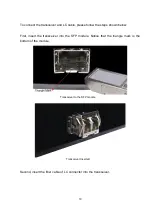
Страница 23: ...20 LC connector to the transceiver...
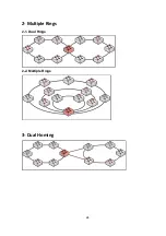
Страница 27: ...24 2 Multiple Rings 2 1 Dual Rings 2 2 Multiple Rings 3 Dual Homing...
Страница 28: ...25 4 Chain 4 1 Single Chain 4 2 Multiple Chains 4 3 Multiple Chains Share Common Ends 4 4 Cascade Chain...
Страница 29: ...26 4 5 Chain in Chain...
Страница 58: ...55 Demo Demo display each topology in different application...
Страница 91: ...88 6 16 1 8 The setting of neighbour switch 6 16 1 9 The setting of none switch...
Страница 96: ...93 ARP Table You can find the MAC addrees of each IP you have ping via this switch in here...
Страница 100: ...97 Straight through cables schematic Cross over cables schematic...
Страница 104: ...101 3 1 1 Command system configuration Parameter N A Description show the information of switch Example...
Страница 119: ...116...


