


11
2.4 LED Indicators
The diagnostic LEDs that provide real-time information of system and optional status are
located on the front panel of the industrial switch. The following table provides the
description of the LED status and their meanings for the switch.
LED
Color
Status
Meaning
PWR
Green
On
The switch unit is power on
Off
No power
PWR1
Green
On
Power 1 is active
Off
Power 1 is inactive
PWR2
Green
On
Power 2 is active
Off
Power 2 is inactive
FAULT
Red
On
Power or port failure
Off
No failure
P1 ~ P12
Link/Ack
On
A network device is detected.
Blinking
The port is transmitting or receiving packets
from the TX device.
Off
No device attached
FDX/COL
On
The port is operating in full-duplex mode.
Blinking
Collision of Packets occurs.
Off
The port is in half-duplex mode or no device
is attached.
Содержание IPES-3408GSFP
Страница 6: ...3 Stability Testing IEC60068 2 32 Free fall IEC60068 2 27 Shock IEC60068 2 6 Vibration...
Страница 23: ...20 LC connector to the transceiver...
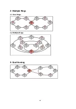
Страница 27: ...24 2 Multiple Rings 2 1 Dual Rings 2 2 Multiple Rings 3 Dual Homing...
Страница 28: ...25 4 Chain 4 1 Single Chain 4 2 Multiple Chains 4 3 Multiple Chains Share Common Ends 4 4 Cascade Chain...
Страница 29: ...26 4 5 Chain in Chain...
Страница 58: ...55 Demo Demo display each topology in different application...
Страница 91: ...88 6 16 1 8 The setting of neighbour switch 6 16 1 9 The setting of none switch...
Страница 96: ...93 ARP Table You can find the MAC addrees of each IP you have ping via this switch in here...
Страница 100: ...97 Straight through cables schematic Cross over cables schematic...
Страница 104: ...101 3 1 1 Command system configuration Parameter N A Description show the information of switch Example...
Страница 119: ...116...


