background image


78


and/or space. A VLAN can only be mapped to one MSTI. An unused MSTI should 

just be left empty. (I.e. not having any VLANs mapped to it.) 

Unmapped VLANs are mapped to the CIST. (The default bridge instance). 


Bridge Priority 

Controls the bridge priority. Lower numeric values have better priority. The bridge 

priority plus the MSTI instance number, concatenated with the 6-byte MAC address 

of the switch forms a Bridge Identifier.   


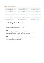
Port 

Port No 

The switch port number of the logical STP port.   


Enabled STP 

Controls whether STP is enabled on this switch port.   


Path Cost 

Controls the path cost incurred by the port. The Auto setting will set the path cost as 

appropriate by the physical link speed, using the 802.1D recommended values. Using 

the Specific setting, a user-defined value can be entered. The path cost is used when 

establishing the active topology of the network. Lower path cost ports are chosen as 

forwarding ports in favour of higher path cost ports. Valid values are in the range 1 to 

200000000.   


Priority 

Controls the port priority. This can be used to control priority of ports having identical 

port cost. (See above).   


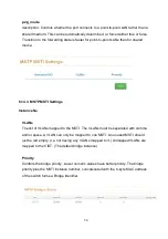
edge_mode 

Controls whether the operEdge flag should start as being set or cleared. (The initial 

operEdge state when a port is initialized). Controls whether the bridge should enable 

automatic edge detection on the bridge port. This allows operEdge to be derived from 

whether BPDU's are received on the port or not. 


Содержание IPES-3408GSFP

Страница 1: ...Lantech IPES 3408GSFP 4 1000 SFP 8 10 100TX L2 PoE Industrial Managed Switch User Manual Beta 04 July 2013...

Страница 2: ...y an STP network cable in demanding electrical environments Examples of demanding indoor environments are where the network cable is located in parallel with electrical mains supply cables or where la...

Страница 3: ...occur in a particular installation If this equipment does cause harmful interference to radio or television reception which can be determined by turning the equipment off and on the user is encourage...

Страница 4: ...2 3ad Port trunk with LACP IEEE802 1d Spanning Tree IEEE802 1w Rapid Spanning Tree IEEE802 1s Multiple Spanning Tree IEEE 802 3ad Link Aggregation Control Protocol LACP IEEE 802 1AB Link Layer Discove...

Страница 5: ...Per unit Power 1 Green Power 2 Green P Fail Red Ethernet port Link Activity Green Speed Green Mini GBIC Link Activity Green Power Supply 48 56VDC Redundant power input with 1500VDC isolation 48VDC is...

Страница 6: ...3 Stability Testing IEC60068 2 32 Free fall IEC60068 2 27 Shock IEC60068 2 6 Vibration...

Страница 7: ...witches which can be compatible with other ITU G 8032 metro switches Support various ring chain topologies Ring covers data multicast packets Pro Ring 2se Self healing recovery in less than 20ms for S...

Страница 8: ...and IPv6 Support Plug and Play function IPv6 Logo Committee certified Perform with following RFCs 1 RFC 2460 IPv6 Specification 2 RFC 4861 Neighbor Discovery for IPv6 3 RFC 4862 IPv6 Stateless Addres...

Страница 9: ...access the switch management and to prevent unauthorized intruder Login Security Supports IEEE802 1X Authentication RADIUS Port Mirror Support 3 mirroring types RX TX and Both packet IGMP Support IGM...

Страница 10: ...one relay output for port breakdown power fail Alarm Relay current carry ability 1A DC24V SNMP Trap 1 Topology Change 2 Power Trap 3 MAC Violation DHCP Provides DHCP Client DHCP Server Port and IP Bi...

Страница 11: ...8 ifAlias Each port allows an alphabetic string of 128 byte assigned as its own unique name via the SNMP or CLI interface...

Страница 12: ...ption In this paragraph it will describe the Industrial switch s hardware spec port cabling information and wiring installation 2 1 Physical Dimension 65 W x 105 D x 152 H mm 2 2 Front Panel Front Pan...

Страница 13: ...10 2 3 Top View The top panel of the Industrial Managed Industrial Switch has one terminal block connector of two DC power inputs and one fault alarm Top Panel of the industrial switch...

Страница 14: ...The switch unit is power on Off No power PWR1 Green On Power 1 is active Off Power 1 is inactive PWR2 Green On Power 2 is active Off Power 2 is inactive FAULT Red On Power or port failure Off No failu...

Страница 15: ...ts section for knowing the information about how to wire the power The power LED on the Industrial switch will light up Please refer to the LED Indicators section for indication of LED lights 5 Prepar...

Страница 16: ...l is screwed on the industrial switch when out of factory If the DIN Rail is not screwed on the industrial switch please see the following pictures to screw the DIN Rail on the switch Follow the steps...

Страница 17: ...sert the top of DIN Rail into the track 2 Then lightly push the DIN Rail into the track 3 Check if the DIN Rail is tightened on the track or not 4 To remove the industrial switch from the track revers...

Страница 18: ...switch loose the screws to remove the DIN Rail 2 Place the wall mount plate on the rear panel of the industrial switch 3 Use the screws to screw the wall mount plate on the industrial switch 4 Use th...

Страница 19: ...insert the power wire 1 Insert AC or DC power wires into the contacts 1 and 2 for power 1 or 5 and 6 for power 2 Tighten the wire clamp screws for preventing the wires from loosing NOTE The wire gauge...

Страница 20: ...e switch will detect the fault status of the power failure or port link failure available for managed model and then forms an open circuit The following illustration shows an application example for w...

Страница 21: ...transceiver used in optical communications for both telecommunication and data communications The SFP slots supporting dual mode can switch the connection speed between 100 and 1000Mbps They are used...

Страница 22: ...llow the steps shown below First insert the transceiver into the SFP module Notice that the triangle mark is the bottom of the module Transceiver to the SFP module Transceiver Inserted Second insert t...

Страница 23: ...20 LC connector to the transceiver...

Страница 24: ...follow the steps shown below First press the upper side of the LC connector to release from the transceiver and pull it out Remove LC connector Second push down the metal loop and pull the transceive...

Страница 25: ...r 4 Network Application This chapter provides some sample applications to help user to have more actual idea of industrial switch function application A sample application of the industrial switch is...

Страница 26: ...h can interact amongst different brands without being tie up by the same supplier to ensure the best investment 3 G 8032 has defined the protocol scheme parameters functions test measures to be unifie...

Страница 27: ...24 2 Multiple Rings 2 1 Dual Rings 2 2 Multiple Rings 3 Dual Homing...

Страница 28: ...25 4 Chain 4 1 Single Chain 4 2 Multiple Chains 4 3 Multiple Chains Share Common Ends 4 4 Cascade Chain...

Страница 29: ...26 4 5 Chain in Chain...

Страница 30: ...Attach the end of RS 232 connector to PC or terminal and the other end of RJ 45 connector to the console port of the switch The connected terminal or PC must support the terminal emulation program 5...

Страница 31: ...e port Baud Rate 115200 bps Data Bits 8 Parity none Stop Bit 1 Flow control None The settings of communication parameters Having finished the parameter settings click OK When the blank screen shows up...

Страница 32: ...nagement supports Internet Explorer 6 0 or later version And it is applied for Java Applets for reducing network bandwidth consumption enhance access speed and present an easy viewing screen 6 2 Prepa...

Страница 33: ...4 Key in the user name and password The default user name and password are the same as root 5 Press Enter or click the OK button and then the home screen of the Web based management appears 6 The swi...

Страница 34: ...Description Display the description of switch The allowed string length is 0 to 255 Location The physical location of this node e g telephone closet 3rd floor The allowed string length is 0 to 255 and...

Страница 35: ...n This function will show you the basic information of switch 6 4 3 IP configuration DHSP client Set the switch as DHCP client it will get the IP address from DHCP server IP Address Input the IP addre...

Страница 36: ...if you need switch to connect with internet please input correct IP address DNS Server IP The IP address of DNS server if you need switch to enable internet service like SNTP please input correct IP a...

Страница 37: ...ne the DNS which will be assigned to DHCP client Lease Time Define the effective time of assigned IP address the DHCP client will apply the IP again from DHCP server when the time is over i System Tim...

Страница 38: ...light 5 hours 7 am CST Central Standard MDT Mountain Daylight 6 hours 6 am MST Mountain Standard PDT Pacific Daylight 7 hours 5 am PST Pacific Standard ADT Alaskan Daylight 8 hours 4 am ALA Alaskan St...

Страница 39: ...ours 8 pm JST Japan Standard USSR Zone 8 9 hours 9 pm EAST East Australian Standard GST Guam Standard USSR Zone 9 10 hours 10 pm IDLE International Date Line NZST New Zealand Standard NZT New Zealand...

Страница 40: ...37 ii SNMP Configuration Community Agent version Choose the SNMP V1 or V2c or V3 String Set the community string of SNMP protocol with read only persimission or read write permission...

Страница 41: ...P trap version V3 User User name Set the user name Security Level Set up the access level you can choose Authentication or Privacy or Both Authentication Protocol Set the authenticated way the default...

Страница 42: ...6 4 6 System Event Log View Logs Logs The action of the system log entry The following action types are supported 0 Login User Login 1 Boot System Boot 2 Din Din Event is triggered 3 Link Change Link...

Страница 43: ...40 Local Log Action Save to Local Save log to local file Remote Syslog Action Log to Remote Syslog Server Save log to Syslog Server Email Action Email Alert Sent log via Email...

Страница 44: ...ction SMS Alert Sent log via SMS service The user must let the switch connect with internet and define the SMS server then the user can use this function Event Action Map Event Actions Select an Event...

Страница 45: ...2 is triggered 4 Power1 Power 1 conditions 5 Power2 Power 2 conditions Link Event Actions Select an Event to Add Fault Relay Configuration Configure Fault Relay on this page Power Failure Power It s t...

Страница 46: ...of a remote digital signal Digital Input When First Second Digital Input function is enabled First Digital Input Second Digital Input will then be available respectively Digital Input Choose the tran...

Страница 47: ...ndition of the ticked checkbox is met port power failure occurs High Low Having focused this radio button DO0 DO1 will output an electrical signal of Low to High when the condition of the ticked check...

Страница 48: ...uration This page displays current port configurations Ports can also be configured here The port settings relate to the currently selected stack unit as reflected by the page header No This is the lo...

Страница 49: ...supported by the specific port is shown Possible speeds are Disabled Disables the switch port operation Auto Let switch port auto negotiating speed with the link partner and selects the highest speed...

Страница 50: ...the same row Type Displays the current speed of connection to the port Link The status of linking Up or Down State It s set by Port Control When the state is disabled the port will not transmit or re...

Страница 51: ...nts of multicast packet 6 5 4 Port Mirroring The Port mirroring is a method for monitor traffic in switched networks Traffic through ports can be monitored by one specific port That means traffic goes...

Страница 52: ...ese 4 types are only for ingress packet The egress rate only supports all type packets Band Width All the ports support port ingress and egress rate control For example assume port 1 is 10Mbps users c...

Страница 53: ...t Enable Enable disable the PoE function of each PoE port Priority Set the priority of power supply if the total power consumption of all PoE ports was over the value of maximum power available the sw...

Страница 54: ...tage The output voltage of each PoE port Main Current The output current of each PoE port Port No The number of each PoE port Link The connection status of each PoE port State The PoE status of the en...

Страница 55: ...52 Output current of each PoE port Voltage Output Voltage of each PoE port Power Power consumption of each PoE port Detection Class The PoE class of each PD device which connect with switch...

Страница 56: ...ield in switch please remember to enable LLDP function before you using this application Topology Status Text View Display each switch in your network by text The Topology was build with the informati...

Страница 57: ...54 Graphic View Display each switch in your network by graphic You can see the topology diagram which build by the LLDP information in here...

Страница 58: ...55 Demo Demo display each topology in different application...

Страница 59: ...have assigned CoS first the port priority will follow the CoS priority first and then other priority rule ToS first the port priority will follow the ToS priority first and the other priority rule Por...

Страница 60: ...the switch This saves the switch from having to re learn a device s MAC address when the disconnected or powered off device is active on the network again You can add modify delete a static MAC addres...

Страница 61: ...o enable the ACL function Direction let the switch check the destination address or source address of packet Address assign the MAC address which you want to deny Mask set the mask to filter the MAC r...

Страница 62: ...authentication and authorization process fails To enable 802 1X you still to fill in the authentication server information Server IP The ip address of the authentication server Server Port The UDP po...

Страница 63: ...be available Enable Web Server When this check box is checked the IP addresses among IP permit list will be allowed to access via web service Enable Telnet Server When this check box is checked the I...

Страница 64: ...s Port untagged port connected to the access link has an untagged VID also called PVID After an untagged frame gets into the access port the switch will insert a four byte tag in the frame The content...

Страница 65: ...ed VID The trunk port will forward the frames of VLAN 1 The trunk port has to be connected to a trunk hybrid port of the other switch Both the tagged VID of the two ports have to be the same 3 Hybrid...

Страница 66: ...xes or PCs can be connected to one subscriber port which is a switch port configured as an MVR receiver port When a subscriber selects a channel the set top box or PC sends an IGMP join message to Swi...

Страница 67: ...tings relate to the currently selected stack unit as reflected by the page header Port No The switch port number of the logical LLDP port Port Id Enter characters to be id name for the logical LLDP po...

Страница 68: ...received Chassis ID The Chassis ID is the identification of the neighbor s LLDP frames Remote Port ID The Remote Port ID is the identification of the neighbor port Port Description Port Description i...

Страница 69: ...d for higher layer entities to assist discovery by the network management This could for instance hold the neighbor s IP address 6 12 3 LLDP Statistics This page provides an overview of all LLDP traff...

Страница 70: ...d of error Frames In The number of LLDP frames received on the port Frames Out The number of LLDP frames transmitted on the port TLVs Discarded Each LLDP frame can contain multiple pieces of informati...

Страница 71: ...down frame is received or when the entry ages out Frames Received In Error The number of received LLDP frames containing some kind of error Frames In The number of LLDP frames received on the port Fra...

Страница 72: ...field Notice2 make sure the IGMP querier switch was in root side of your network if not please set IGMP router port to let switch know which uplink connection was dedicate to the path to the IGMP quer...

Страница 73: ...the Layer 3 multicast device or IGMP querier If an aggregation member port is selected as a router port the whole aggregation will act as a router port Fast Leave Enable the fast leave on the port 6 1...

Страница 74: ...umber of Received Queries V1 Reports Received The number of Received V1 Reports V2 Reports Received The number of Received V2 Reports V3 Reports Received The number of Received V3 Reports V2 Leaves Re...

Страница 75: ...odically transmits CDP frames to its neighbours for having the network discovery information up to date The interval between each CDP frame is determined by the Tx Interval value Valid values are rest...

Страница 76: ...P port Enabled The switch will send out CDP information and will analyze CDP information received from neighbors 6 14 2 CDP Status Statistics Total Packets Output The number of CDP frames transmitted...

Страница 77: ...he neighbor unit Device ID The Device ID is the identification of the neighbor s CDP frames Platform Platform is the description advertised by the neighbor unit Software Version Software Version is th...

Страница 78: ...as well as the VLAN to MSTI mapping configuration in order to share spanning trees for MSTI s Intra region The name is at most 32 characters Revision The revision of the MSTI configuration named abov...

Страница 79: ...the initial value of remaining Hops for MSTI information generated at the boundary of an MSTI region It defines how many bridges a root bridge can distribute its BPDU information to Valid values are i...

Страница 80: ...77 6 14 1 3 Remember to press Apply 6 14 1 4 Save setting 6 14 2 CIST Settings Bridge configuration VLANs Mapped The list of VLANs mapped to the MSTI The VLANs must be separated with comma...

Страница 81: ...tting will set the path cost as appropriate by the physical link speed using the 802 1D recommended values Using the Specific setting a user defined value can be entered The path cost is used when est...

Страница 82: ...stance No VLANs The list of VLANs mapped to the MSTI The VLANs must be separated with comma and or space A VLAN can only be mapped to one MSTI An unused MSTI should just be left empty I e not having a...

Страница 83: ...dge Root Port The switch port currently assigned the root port role Root Cost Root Path Cost For the Root Bridge it is zero For all other Bridges it is the sum of the Port Path Costs on the least cost...

Страница 84: ...P port Role The current STP port role of the port The port role can be one of the following values AlternatePort BackupPort RootPort DesignatedPort Disabled State The current STP port state of the por...

Страница 85: ...Trunking function Port Members Each switch port is listed for each group ID Select a radio button to include a port in an aggregation or clear the radio button to remove the port from the aggregation...

Страница 86: ...roup but will join if other port leaves Meanwhile it s LACP status is disabled System ID The ID of each Trunking group Port Members Each switch port is listed for each group ID Select a radio button t...

Страница 87: ...priority2 value to be used as a tie breaker between two devices that are otherwise equally matched in the default criteria For example you can use priority2 value to give a specific switch priority o...

Страница 88: ...ges The range is 1 second to 1 second The default is 1 second Delay Request Interval specify the time recommended to the member devices to send delay request messages when the port is in the master st...

Страница 89: ...either RPL owner or RPL Neighbor Type Type of Protecting ring It can be either major ring or sub ring Ring Port 0 This will create a Port 0 of the switch in the ring Ring Port 1 This will create Ring...

Страница 90: ...the port0 of owner switch must connect with the neighbour switch 6 16 1 6 After enable the ring of G8032 the port0 of owner switch will be blocked at first For safe issue we suggest the user to finis...

Страница 91: ...88 6 16 1 8 The setting of neighbour switch 6 16 1 9 The setting of none switch...

Страница 92: ...up State ERPS state according to State Transition Tables in G 8032 Role It can be either RPL owner or RPL Neighbour Ring Port 0 true ring port 0 is blocking false ring port 0 is not blocking Ring Port...

Страница 93: ...ore Settings Backup You can download the backup configuration of the switch Settings Restore You can copy the backup configuration of the switch to the startup configuration on this page The new start...

Страница 94: ...the configuration of the switch on this page Only the IP configuration is retained The new configuration is available immediately which means that no res tart is necessary 6 18 3 Restart device Reboot...

Страница 95: ...re Upgrade Update the switch with the firmware file which on your desktop 6 18 5 Diagnostics PING Address Set the IP address which you want to ping Count Set the times of Ping Packet Size set the size...

Страница 96: ...93 ARP Table You can find the MAC addrees of each IP you have ping via this switch in here...

Страница 97: ...length of any twisted pair connection does not exceed 100 meters 328 feet Diagnosing LED Indicators To assist in identifying problems the switch can be easily monitored through panel indicators which...

Страница 98: ...d crossover cable schematic 10 100BASE TX Pin outs With10 100BASE TX cable pins 1 and 2 are used for transmitting data and pins 3 and 6 for receiving data RJ 45 Pin Assignments Pin Number Assignment 1...

Страница 99: ...ng two figures show the 10 100Base TX cable schematic Straight through cable schematic Cross over cable schematic 10 100 1000Base TX Pin outs The following figure shows the 10 100 1000 Ethernet RJ 45...

Страница 100: ...97 Straight through cables schematic Cross over cables schematic...

Страница 101: ...dy turn on the PC and run a terminal emulation program or Hyper Terminal and configure its communication parameters to match the following default characteristics of the console port Baud Rate 115200...

Страница 102: ...press Enter and the Main Menu of console management appears Please see below figure for login screen Notice if you forgot the password you can access the switch via console port and input lantech lan...

Страница 103: ...et utility to access switch IP and make sure the socket was set as 23 all the commands under Telnet mode were the same as the Console mode 3 Commands 3 1 System Command system Parameter N A Descriptio...

Страница 104: ...101 3 1 1 Command system configuration Parameter N A Description show the information of switch Example...

Страница 105: ...e contact windows to jacky lantechcom tw 3 1 3 Command system name Parameter N A Description display or fix the system name Example 3 1 4 Command system location Parameter N A Description display or f...

Страница 106: ...system DHCP server Parameter enable disable enable or disable DHCP server range_low range_high set the IP range netmask set submask gateway set gateway dns set DNS server lease_time set the lease time...

Страница 107: ...ess Example 3 1 10 Command system netsettingIPv4 Parameter IpAddr set IP address netmask set netmask gatewayip set gateway dnsip set DNS server Description set the IP detail of switch Example 3 1 11 C...

Страница 108: ...all but keep original IP address and account keep_ip restore all but keep original IP address keep_account restore all but keep original account Description restore the setting of switch to factory de...

Страница 109: ...ress Example 3 1 18 Command system memory Parameter N A Description display the status of used switch memory Example 3 1 19 Command system configaccess Parameter export import export or import the set...

Страница 110: ...irmware file support TFTP and FTP and HTTP protocol Description update switch firmware Example 3 2 LLDP Command LLDP Parameter N A Description Enter the LLDP mode Example 3 2 1 Command LLDP configurat...

Страница 111: ...LLDP information of the dedicated port enabledRxTx enable Tx and Rx of LLDP function with dedicated port enabledTxOnly enable Tx only of LLDP function with dedicated port enabledRxOnly enable Rx only...

Страница 112: ...tion set the interval time of LLDP Example 3 2 5 Command LLDP timetolive Parameter N A Description display the alive time of LLDP information Example 3 2 6 Command LLDP info Parameter N A Description...

Страница 113: ...110 3 2 7 Command LLDP statistics Parameter N A Description display the detail information of LLDP settings Example 3 3 Port Command port Parameter N A Description Enter the port mode Example...

Страница 114: ...3 3 1 Command port configuration Parameter N A Description display the setting of each port Example 3 3 2 Command port status Parameter N A Description display the connection status of each port Exam...

Страница 115: ...port_list choose which port you want to enable or diasble enable disable enable disable Description enable or disable switch port Example 3 3 4 Command port description Parameter N A Description disp...

Страница 116: ...iption display the speed of each port Example 3 3 6 Command port flowcontrol Parameter port_list choose which port you want to enable or diasble enable disable enable disable Description enable or dis...

Страница 117: ...which port you want to set the ingress rate rate kbps set the ingress rate of these packet as below broadcast multicast unicast broad_uni broad_multi multi_uni uni_broad_multi Description set the ing...

Страница 118: ...oose which port you want to set the ingress rate rate kbps set the ingress rate Description set the egress rate of the dedicated port Example 3 3 9 Command port statistics Parameter N A Description di...

Страница 119: ...116...

Отзывы: