5
X
RS-232,485 + 2
X
E
THERNET
/2 M
BIT
/
S
G.703 (G.704) M
ULTIPLEXER
O
PERATING
M
ANUAL
IOA81-1E
4
August 2004
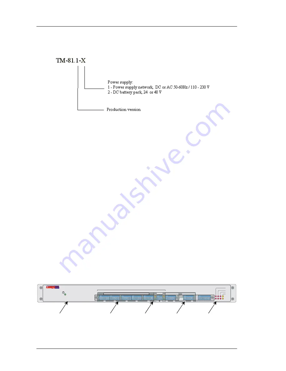
1.4 Marking
Note: Each time a symbol containing the letter "X" instead of its corresponding digit appears
in the Manual, it means that the feature specified in this part of the symbol is insignifi-
cant for the parameter being discussed and may be equal to any value from the above-
mentioned range. However, the device symbol specified for ordering purposes must
contain only the digits following the manufacturer symbol "TM".
2 Connectors and LED indicators
2.1 Front
Panel
The following controls are located on the front panel of the device:
•
Switches for configuring the device,
•
LEDs for signalling the status of G.703 and 10BASE-T channels,
•
LED for signalling the power on.
1 -
Power On LED
2 -
Switches for configuration of RS component channels
3 -
Switches for configuration of ETHERNET component channels,
Status signalling for Ethernet channels (RCV- reception of frames at the port, LNK – informs whether
the port is connected correctly)
4 -
Switches for configuration of E1 2048 kbit/s channels
5 -
Status signalling for E1 ports
TM-81
MULTIPLEXER 7x64k/2M
T R I B U T A R Y C H A N N E L C O N F I G U R A T I O N
TM-81
B
A
AIS
10
-3
LOF
LOS
G.703
CONFIGURATION
B
A
Droop
LNK
RCV
LNK
RCV
C
C
C
C
C
C
C
LP
C
C
C
TS
C
1
1
1
3
4
5
7
7
7
6
2
CHANNEL DIRECTION
10BASE-T
MODE OF OPERATION
4 5 6 7 8
1 2 3
ON
4 5 6 7 8
1 2 3
ON
4
1 2 3
ON
4 5 6 7 8
1 2 3
ON
4 5 6 7 8
1 2 3
ON
4 5 6 7 8
1 2 3
ON
4 5 6 7 8
1 2 3
ON
4 5 6 7 8
1 2 3
ON
4 5 6 7 8
1 2 3
ON
9 10
RS232/485
Continue
Droop &
1 2 3 4 5
Fig. 3.
Front panel


