


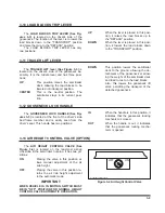


3-17 AXLE LIFT CONTROL VALVE (OPTION)
The
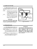
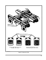
AXLE LIFT CONTROL VALVE (See Fig-
ure 3-7)
is located on the rear airbag crosstube. It
is used to control the axle lift system and has two
positions.
UP
Placing the control valve in this posi-
tion raised the associated axle up off
the surface of the ground.
DOWN
Placing the control valve in this posi-
tion lowers the associated axle to the
ground to assist in load carrying.
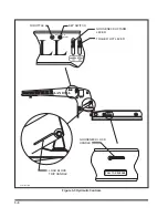
3-18 HYDRAULIC POWER SUPPLY ENGINE THROTTLE (OPTION)
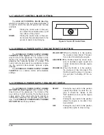
The
HYDRAULIC POWER SUPPLY ENGINE
THROTTLE (See Figures 3-3)
is located on the
driver's side of the gooseneck. The function of the
throttle is to control the speed at which the engine
powering the hydraulic system is running. This
control will only be present on semitrailers contain-
ing the optional self-contained hydraulic engine
package.
The
HYDRAULIC POWER SUPPLY ENGINE
THROTTLE
is a variable control with adjustable
settings.
PULLED OUT
When the throttle is in this position,
the engine is fully choked. This posi-
tion is used for starting the engine.
ADJUSTED IN
The throttle should be turned clock-
wise to decrease engine speed and
counter clockwise to increase engine
speed.
PUSHED IN
When the throttle is in this position,
the engine is at low idle speed. The
throttle should be placed in this posi-
tion just prior to shutting off the en-
gine.
3-19 HYDRAULIC POWER SUPPLY ENGINE KEY SWITCH
The
HYDRAULIC POWER SUPPLY ENGINE
KEY SWITCH (See Figures 3-3)
is located on the
driver's side of the gooseneck. The function of the
key switch is to start and stop the hydraulic power
supply engine. This control will only be present on
semitrailers containing the hydraulic engine pack-
age. The
HYDRAULIC POWER SUPPLY ENGINE
KEY SWITCH
has three positions.
START
Placing the key switch in this position
causes the starter to crank the en-
gine. It should be release to the
"ON" position as soon as the engine
is running.
ON
Placing the key switch in this position
allows the engine to run after it has
been started.
OFF
Placing the key switch in this position
causes the engine to stop running.
3-12
UP
DOWN
axle lift control valve
Figure 3-7 Axle Lift Control Valve
Содержание 325C
Страница 2: ......
Страница 8: ......
Страница 12: ......
Страница 36: ......
Страница 44: ...4 8 Figure 4 3 Models 325 326 327 329C Wiring Diagram...
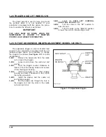
Страница 54: ...4 18 Figure 4 13 Checking Axle Alignment Figure 4 14 Examples of Camber...
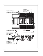
Страница 59: ...4 23 Figure 4 17 Axle and Brake Assembly...
Страница 68: ......
Страница 78: ...NOTES 5 10...
Страница 79: ......


