


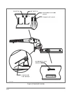


3-10 LOAD BLOCKS TRIP LEVER
The
LOAD BLOCKS TRIP LEVER (See Fig-
ures 3-3)
is located on the driver's side of the
gooseneck. The function of the lever is to lower the
load blocks down to the "TRANSPORT" position
and raise them up to the "DETACH" position.
The LOAD BLOCKS TRIP LEVER has only
two positions:
UP
When the lever is placed in this posi-
tion, it raises the load blocks up to
the "DETACH" position.
DOWN
When the lever is placed in this posi-
tion, it lowers the load blocks down
to the "TRANSPORT" position.
3-11 TRAILER LIFT LEVER
The
TRAILER LIFT lever (See Figure 3-3)
is
located on the driver’s side of the gooseneck as-
sembly. It is the middle lever and has three posi-
tions:
UP
This position raises the semitrailer
deck, allowing the load blocks to be
lowered into transport position.
CENTER
This is the neutral position. The
semitrailer stays in its current posi-
tion.
DOWN
This position lowers the semitrailer
deck to the ground, allowing the de-
tachment of the gooseneck or allow-
ing the weight of the semitrailer deck
and load to rest on the load blocks.
Also, this lowers the gooseneck lift
arms, permitting the transport of the
detached gooseneck.
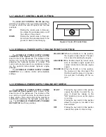
3-12 GOOSENECK LOCK HANDLE
The
GOOSENECK LOCK HANDLE (See Fig-
ures 3-3)
is located at the front of the driver's side
bed frame member and is easily seen from the
driver's seat. This handle has two positions:
IN
When the handle is in this position, it
indicates that the gooseneck locking
mechanism is closed.
OUT
When the handle is out, it indicates
that the gooseneck locking mecha-
nism is opened.
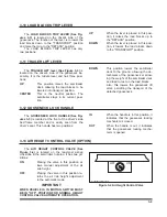
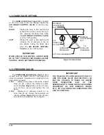
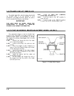
3-13 AIR HEIGHT CONTROL VALVE (OPTION)
The
AIR HEIGHT CONTROL VALVE (See
Figure 3-4)
is located on the rear-most airbag
crosstube in the semitrailer trunnion. It has two po-
sitions:
ON
Placing the valve in this position al-
lows manual adjustment of the air
ride height.
OFF
Placing the valve in this position re-
turns the air ride height adjustment
to the automatic mode.
IMPORTANT
WHEN VEHICLE IS IN MOTION, SWITCH MUST
BE IN "OFF" POSITION FOR NORMAL HEIGHT
CONTROL VALVE AUTOMATIC OPERATION.
3-9
OFF
ON
air height control valve
Figure 3-4 Air Height Control Valve
Содержание 325C
Страница 2: ......
Страница 8: ......
Страница 12: ......
Страница 36: ......
Страница 44: ...4 8 Figure 4 3 Models 325 326 327 329C Wiring Diagram...
Страница 54: ...4 18 Figure 4 13 Checking Axle Alignment Figure 4 14 Examples of Camber...
Страница 59: ...4 23 Figure 4 17 Axle and Brake Assembly...
Страница 68: ......
Страница 78: ...NOTES 5 10...
Страница 79: ......


