


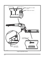


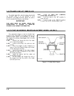

3-14 HAND VALVE (OPTION)
The
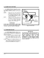
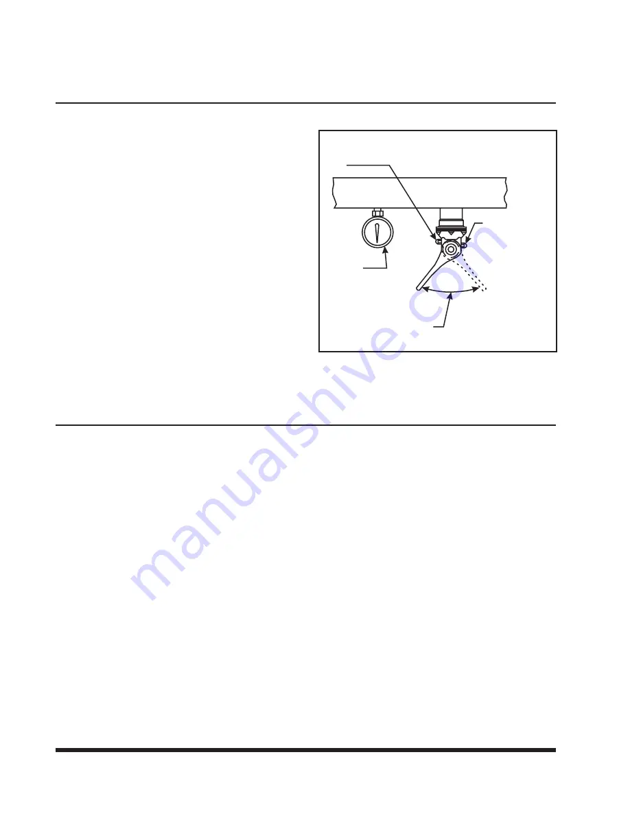
HAND VALVE (See Figure 3-5)
is located
on the front side of rear tail channel beside the
AIR HEIGHT CONTROL VALVE
. It has two posi-
tions:
RIGHT
Placing the valve in this position will
exhaust the air from the air ride sys-
tem, lowering the trailer deck when
the
AIR HEIGHT CONTROL VALVE
is in the "ON" position.
LEFT
Placing the valve in this position will
increase the air pressure in the air
ride system, raising the trailer deck
when the
AIR HEIGHT CONTROL
VALVE
is in the "ON" position.
IMPORTANT
WHEN VEHICLE IS IN MOTION, SWITCH MUST
BE IN "OFF" POSITION FOR NORMAL HEIGHT
CONTROL VALVE AUTOMATIC OPERATION.
3-15 PRESSURE GAUGE
The
PRESSURE GAUGE (See Figure 3-5)
is
located near the HAND VALVE. This gauge pro-
vides air pressure information for adjusting the air
ride system manually.
3-15.1
Minimum air pressure should be at least
three (3) psi. Loosen the minimum adjust-
ment nut
(See Figure 3-5)
, set the air pres-
sure at three (3) psi and tighten the nut
again.
3-15.2
Maximum air pressure should be no
more than 85 psi. Loosen the maximum ad-
justing nut
(See Figure 3-5)
, set the air pres-
sure at 85 psi and tighten the nut again.
IMPORTANT
THE TRAILER LIFT LEVER (SEE SECTION 3-11)
AND THE HAND VALVE (SEE SECTION 3-14)
MAY BE UTILIZED TO RAISE OR LOWER
THEIR
RESPECTIVE
END
OF
THE
SEMITRAILER TO CLEAR OBSTACLES DURING
TRANSPORT
(I.E.
LOW
BRIDGES,
CURBS,
ETC.) BY FOLLOWING THE DIRECTIONS FOR
USE OF CONTROLS.
3-10
hand valve
MAXIMUM
ADJUSTMENT
NUT
AIR
PRESSURE
GAUGE
90 TOTAL MOVEMENT
MINIMUM
ADJUSTMENT
NUT
TO
INCREASE
PRESSURE
TO
EXHAUST
PRESSURE
O
Figure 3-5 Hand Valve
Содержание 325C
Страница 2: ......
Страница 8: ......
Страница 12: ......
Страница 36: ......
Страница 44: ...4 8 Figure 4 3 Models 325 326 327 329C Wiring Diagram...
Страница 54: ...4 18 Figure 4 13 Checking Axle Alignment Figure 4 14 Examples of Camber...
Страница 59: ...4 23 Figure 4 17 Axle and Brake Assembly...
Страница 68: ......
Страница 78: ...NOTES 5 10...
Страница 79: ......


