background image

LANCOM GS

-

1224 and LANCOM GS

-

1224P

쮿

 Chapter 2: Installation

12

EN

2.3.2

Connectors on the back of the LANCOM GS-1224 

The following connectors are located on the rear of the device.


Connector for the power supply cable.

2.4

Mounting and connecting up the LANCOM Switch

Installating the LANCOM Switch involves the following steps:

Mounting

 – The device is designed for mounting in an available 19” unit 

in a server cabinet. If necessary fix the rubber pads to the underside of the 
device to prevent any scratching to other equipment.

C

Ensure that the device has sufficient ventilation to prevent damage 
from excessive heat build-up.

LAN connection

 – Connect the network devices to the ports of the LAN-

COM Switch by means of a suitable twisted-pair cable (TP cable). The con-
nectors automatically detect the avalable data transfer speeds and the pin 
assignment (autosensing). 

I

Use only standard TP cables of category CAT 5e or better with a maxi-
mum length of 100 m to ensure the best possible transfer of data. 
Cross-over cables can be used thanks to the auto-sensing function.

I

If optical connections are to be used, additional modules can be 
purchased as accessories.

Supply power and switch on

 – Supply power to the device by means of 

the IEC power cable. 

Ready for operation?

 – After a brief self-test, the power LED lights up 

continuously. Green LAN-LINK LEDs show which LAN connectors are 
being used for a connection.

LANCOM GS-1224

Содержание GS-1224P

Страница 1: ...0411 LANCOM Systems GmbH Adenauerstr 20 B2 52146 W rselen Germany E Mail info lancom eu Internet www lancom eu LANCOM GS 1224 LANCOM GS 1224P c o n n e c t i n g y o u r b u s i n e s s...

Страница 2: ...LANCOM GS 1224 LANCOM GS 1224P...

Страница 3: ...ered trademarks of Microsoft Corp The LANCOM Systems logo LCOS and the name LANCOM are registered trademarks of LANCOM Systems GmbH All other names or descriptions used may be trademarks or registered...

Страница 4: ...atts from the PoE supply can be flexibly divided between the ports Model variants This documentation is intended for LANCOM Switch users The following models are available The LANCOM GS 1224 without P...

Страница 5: ...n are constantly available for download In addition LANCOM Support is available For telephone numbers and contact addresses for LANCOM Support please refer to the enc losed leaflet or the LANCOM Syste...

Страница 6: ...rs LEDs and buttons on the LANCOM GS 1224 11 2 3 2 Connectors on the back of the LANCOM GS 1224 12 2 4 Mounting and connecting up the LANCOM Switch 12 2 5 Software installation 13 2 5 1 Starting the s...

Страница 7: ...ror Configuration 47 4 2 12 QoS Quality of Service Configuration 48 4 2 13 Filter 51 4 2 14 Rate Limit 52 4 2 15 Storm Control 53 4 2 16 SNMP 54 4 3 Monitoring 56 4 3 1 Detailed Statistics 56 4 3 2 LA...

Страница 8: ...cation current limit and other necessary functions It also supports high safety with short circuit protection and power out auto detection to PD The 10 100 1000 Mbps TP Ports are standard Ethernet por...

Страница 9: ...ct Besides SNMP agent will actively issue TRAP information when happe ned The device supports MIB II RFC1213 Bridge MIB RFC1493 Interface Group MIB RFC2863 IGMP Snooping Support IGMP version 2 RFC 223...

Страница 10: ...ion IEEE 802 1q VLAN DHCP Broadcasting Suppression to avoid network suspended or crashed Trap event while monitored events happened Default configuration which can be restored to overwrite the current...

Страница 11: ...ng please take up immediate contact to your dealer or to the address on the delivery note supplied with your device 2 2 System requirements Computers that connect to a LANCOM must meet the following m...

Страница 12: ...f no network connection can be established to the connected device 10 100 1000 Mbps LED Constant green when the 1000 Mbps mode is active Constant orange when the 100 Mbps mode is active Off when the 1...

Страница 13: ...ve heat build up LAN connection Connect the network devices to the ports of the LAN COM Switch by means of a suitable twisted pair cable TP cable The con nectors automatically detect the avalable data...

Страница 14: ...ction if you use your LANCOM Switch exclusively with computers running operating systems other than Windows 2 5 1 Starting the software setup Place the supplied data medium CD DVD into your drive The...

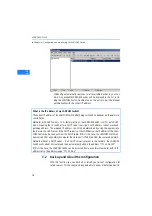
Страница 15: ...e this to start the Web based configuration of a LANCOM Switch With LANmonitor you can use a Windows computer to monitor all of your LANCOM devices This program displays all important status infor mat...

Страница 16: ...uctions for configuring the device with WEBconfig are avai lable in the chapter Web based configuration There are two ways of starting the configuration by browser If you know the device s IP address...

Страница 17: ...tellation Networks with DHCP server In its factory settings the LANCOM Switch is set for auto DHCP mode meaning that it searches for a DHCP server to assign it an IP address subnet mask and gateway ad...

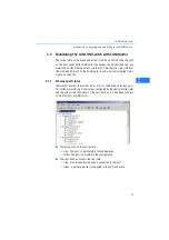
Страница 18: ...rtant infor mation on the ports 3 3 1 Ethernet port status LANmonitor displays the current status of all of the device s Ethernet ports This includes monitoring of the state as configured by the admin...

Страница 19: ...default values of the managed switch are listed in the table below Web Smart Switch supports a simplified user management function which allows only one administrator to configure the switch at one t...

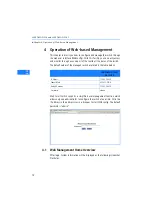
Страница 20: ...s for the optional SFP modules show a demonstration of the module if it is installed Ports without installed SFP modules show covered plates On the left side the main menu tree for web management is l...

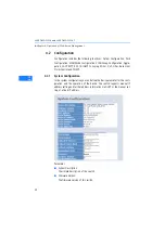
Страница 21: ...1X IGMP Snooping Mirror QoS Filter Rate Limit Storm Control and SNMP 4 2 1 System Configuration In the system configuration you can define the basic parameter for the confi guration and the operation...

Страница 22: ...P address of the DHCP server Lease Time Left Show the lease time left of DHCP client Device Name Set a special name for this switch Up to 16 characters are allowed in this parameter Any alphanumeric c...

Страница 23: ...efault 172 23 56 254 Management VLAN Shows the ID of the management VLAN Password Set a password for this switch Up to 16 characters are allowed in this parameter Any alphanumeric character is accepta...

Страница 24: ...meter Enable Jumbo Frames Jumbo frames are not standardized and oversized frames This function support jumbo frames of up to 9600 bytes Default disable Power Saving Mode This function supports Power S...

Страница 25: ...e media supports Flow Control You can tick the check box to enable flow control If flow control is set to Enable both parties can send a PAUSE frame to the transmitting device s if the receiving port...

Страница 26: ...is linked to the port on the switch exceeding the Class setting of the powered device Short Circuit Port Off The switch will stop supplying the power to the port if it detects that the powered device...

Страница 27: ...ate Enable allows power supply while a device is linked to the port Disable means the port does not support PoE functions Priority Choices are Normal Low and High The former being the default choice I...

Страница 28: ...ode Parameter VLAN Mode Port based A port based VLAN defines its members by port Any packet coming in or going out from any port of a port based VLAN will be accepted No filtering criterion applies in...

Страница 29: ...VLAN ID A valid VLAN ID is 1 up to 4094 You can create up to 24 Tag VLAN groups As soon as the VLAN mode is set on tag based the setting double tag mode will be offered If the double tag mode is activ...

Страница 30: ...d VLAN mode the display auto matically changes to the configuration of the tag based VLAN groups Metro Mode The Metro mode is a quick method to configure port based VLANs Metro mode can be activated f...

Страница 31: ...m certain groups if needed 4 2 5 VLAN Group Configuration Shows the information of VLAN Groups and allows administrators to maintain them by modifying and deleting each VLAN group The display differs...

Страница 32: ...Adds a new port based or tag based VLAN Modify Click on Modify to edit the selected VLAN Delete Click on Delete to remove the selected VLAN VLAN group configuration Parameter ID VLAN ID ID of the VLAN...

Страница 33: ...S 1224P Chapter 4 Operation of Web based Management 32 EN VLAN Port Configuration In tag based mode you can define further settings for each port Please click the Port Config button in the list of tag...

Страница 34: ...forwarded untagged If double tags are detected the outer tag will be removed This option is generally used if end devices are connected to the port Trunk Packets on this port are forwarded using the...

Страница 35: ...g Configuration is used to configure the set tings of Link Aggregation You can bundle more than one port by same speed full duplex and the same MAC to be a single logical port thus the logical port ag...

Страница 36: ...orts for group 1 are selected and the settings are stored with Apply 4 2 7 LACP Smart Web Switch supports Link Aggregation Control Protocol LACP LACP is a standard network protocol IEEE 802 3ad which...

Страница 37: ...stem Default 32768 Hello Time Hello Time is the time interval in which the switch tells the following devices in the spanning tree with a hello packet that it is still active If for example the LANCOM...

Страница 38: ...ust tick the check box beside the port x to enable RSTP protocol then press Apply Edge An Edge Port is a port connected to a device that knows nothing about STP or RSTP Usually the connected device is...

Страница 39: ...his her account name for authentication and waits for gaining authorization before sending or receiving any packets from a 802 1x enabled port Before the devices or end stations can access the network...

Страница 40: ...ill unconditionally pass the packets with PAE group MAC address which has the value of 01 80 c2 00 00 03 and will not be forwarded by the MAC bridge at any time Authentication server A device provides...

Страница 41: ...to access the services on device B and C first it must exchange the authentication message with the authenticator on the port it connected via EAPOL packet The authenticator transfers the supplicant s...

Страница 42: ...onse Identity to the authentica tor The authenticator will embed the user ID into RADIUS Access Request command and send it to the authentication server for confirming its identity After receiving the...

Страница 43: ...nauthorized The 802 1X enabled is the type of authentication supported by the switch In this mode the devices connected to this port once a supplicant is autho rized can access the network resources t...

Страница 44: ...key between authentication server and authenticator It is a string with the length of 1 15 characters The character string may con tain upper case lower case and 0 9 It is character sense It is not al...

Страница 45: ...thorization Re authenticate Using this function all devices connected to this port will have to re authenticate with username and password when the reauthentication period expires Re authenticate All...

Страница 46: ...want to show of 802 1X statistics the screen include Authenticator counters backend Authenticator counters dot1x MIB counters and Other statistics Parameters You can enable or disable the reauthentica...

Страница 47: ...time period can not be zero Default 3600 seconds EAP timeout 1 255 s A timeout condition in the exchange between the authenticator and the supplicant Valid range 1 255 Default 30 seconds 4 2 10 IGMP S...

Страница 48: ...n handle IGMP requests in the network and learns the membership of certain multicast groups if neces sary Default enable IGMP Querying Enabled If this function is enabled the switch can distribute IGM...

Страница 49: ...SCP Differentiated Services Code Point on Layer 3 of network framework QoS Configuration While setting QoS function please select the QoS Mode in drop down menu at first Then you can use 802 1p Priori...

Страница 50: ...ber for 802 1p Configuration 802 1p Configuration Each Priority can select any of the Queues In Default Priority 0 is mapping to Queue normal Priority 1 is mapping to Queue low Prio rity 2 is mapping...

Страница 51: ...c values are provided Custom All Low Priority All Normal Priority All Medium Priority and All High Priority The QoS setting applies to all ports on the switch if one of the follo wing values is select...

Страница 52: ...sabled Disabled Allows all IP Addresses to login and manage the switch Static Allows the IP Addresses set by the administrator to login and manage the switch DHCP Allows the IP Address distributed by...

Страница 53: ...Data Rate field Pause frames are also generated if flow control is enabled The format of the packet limits to unicast broadcast and multicast Valid values are multiples 0 to 31 of the traffic rate un...

Страница 54: ...d and values of storm control are exceeded multicast and broadcast frames will be dropped Parameter ICMP Rate Enables the ICMP Storm capability The setting range is 1k 1024k per second If the amount o...

Страница 55: ...managed devices SNMP is a protocol that is used to govern the transfer of information between the SNMP manager and agent and traverses the Object Identity OID of the Management Information Base MIB de...

Страница 56: ...Hence the requesting network management unit cannot access the device with a different community name via the SNMP protocol If they both have the same community name they can talk to each other The co...

Страница 57: ...Link Up and or Link Down 4 3 Monitoring There are five functions contained in the monitoring function Detailed Stati stics LACP Status RSTP Status IGMP Status and Ping Status 4 3 1 Detailed Statistic...

Страница 58: ...meter Rx Packets The number of packets received Rx Octets Total received bytes Rx High Priority Packets Number of Rx packets classified as high priority Rx Low Priority Packets Number of Rx packets cl...

Страница 59: ...lassified as low priority Tx Broadcast Shows the number of transmitted broadcast packets Tx Multicast Shows the number of transmitted multicast packets Tx Broad and Multicast Shows the number of trans...

Страница 60: ...in good and bad packets transmitted Tx 1024 Bytes Number of 1024 max_length byte frames in good and bad packets trans mitted Rx CRC Alignment Number of Alignment errors and CRC error packets received...

Страница 61: ...window shows LACP information and status for all ports at the same time Within the IEEE specification the Link Aggregation Control Pro tocol LACP provides a method to control the bundling of several p...

Страница 62: ...ty setting and bridge ID of the switch which stands for the MAC address of this switch Hello Time Shows the current hello time of the root bridge Max Age Shows the current root bridge maximum age time...

Страница 63: ...from a host for a given multicast group the switch adds the host s port number to the multicast list for that group When the switch hears an IGMP Leave it removes the host s port from the table entry...

Страница 64: ...outers on the network It shows the leaves number 4 3 5 Ping Status Sets up target IP address for ping function and display ping status Ping test function is a tool for detecting if the target device i...

Страница 65: ...o start after you set the parameters Ping Results Target IP address Shows the active target IP address Status Shows the result of the ping status Received replies Shows the received replies number of...

Страница 66: ...t values when Factory Default function is perfor med If you want to restore all configurations including the IP address setting to the factory default please press the RESET button on the front panel...

Страница 67: ...are three possibilities to log out or be logged out Auto Logout If Auto Logout is ON and no action no key stroke is done for the time in minutes you set up in the Auto Logout Timer the switch will lo...

Страница 68: ...sting Supports IGMP snooping Spanning Tree Protokoll STP Rapid STP 802 1d 1w 802 3af Features Ports 24x 802 3af PoE ports Power 185 Watt total power with dynamic load balancing on all ports i e up to...

Страница 69: ...24P Chapter 5 Appendix 68 EN Accessories 1000Base SX SFP module LANCOM SFP SX LC1 item no 61556 1000Base LX SFP module LANCOM SFP LX LC1 item no 61557 Service 5 years Support Via Hotline and Internet...

Страница 70: ...s that the devices of the type described in this documentation are in agreement with the basic requirements and other relevant regulations of the 1995 5 EC directive The CE declarations of conformity...

Страница 71: ...52146 W rselen Germany E Mail info lancom eu Internet www lancom eu LANCOM GS 1224 LANCOM GS 1224P c o n n e c t i n g y o u r b u s i n e s s LC GS1224 MANUAL_cover indd 1 LC GS1224 MANUAL_cover indd...

Отзывы: