background image

RM024 User Manual 

Version 2.3


Americas: +1-800-492-2320 Option 2 
Europe: +44-1628-858-940 
Hong Kong: +852-2923-0610 

www.lairdtech.com/wireless


43 

CONN-GUIDE-RAMP24-0413 


Command: 

<0xCC> <0x0A> <Location> 

Number of Bytes Returned: 

Response: 

<0xCC> <Value> 

Parameter Range: 

<Location>: [Dependant of parameter] 
<Value>: 0x00-0xFF 

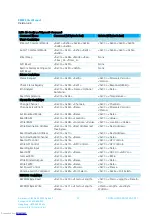
Write IRAM 

This command is used to change the IRAM contents. The IRAM contains the active (in memory) copy of the 
EEPROM parameters. Some of these fields are available for reading and writing to provide on-the-fly 
instantaneous setting of parameters. Parameters changed via the IRAM commands take effect immediately 
and remain in effect until the radio is reset. IRAM changes do not persist after a reboot. 

Restrictions on the specific IRAM parameters are the same as for the EEPROM parameters. 

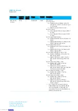
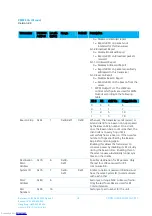
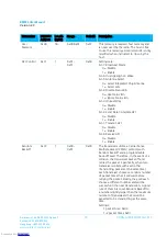
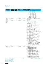
Available locations in IRAM are: 

Name 

Address 

Range Refresh 

0x3D 

RF Channel 

0x41 

Interface Timeout 

0x58 

RF Packet Size 

0x5A 

CTS_On_H 

0x5C 

CTS_On_L 

0x5D 

CTS_Off_H 

0x5E 

CTS_Off_L 

0x5F 

Max Power 

0x63 

Destination MAC Address 3 

0x72 

Destination MAC Address 2 

0x73 

Destination MAC Address 1 

0x74 

Destination MAC Address 0 

0x75 

System ID 

0x76 


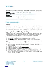
Command: 

<0xCC> <0x0B> <Location> <Value> 

Number of Bytes Returned: 

Response: 

<0xCC> <Location> <Value> 

Parameter Range: 

<Location>: [Dependant of parameter] 
<Value>: 0x00-0xFF 


Downloaded from

Arrow.com.

Downloaded from

Arrow.com.

Downloaded from

Arrow.com.

Downloaded from

Arrow.com.

Downloaded from

Arrow.com.

Downloaded from

Arrow.com.

Downloaded from

Arrow.com.

Downloaded from

Arrow.com.

Downloaded from

Arrow.com.

Downloaded from

Arrow.com.

Downloaded from

Arrow.com.

Downloaded from

Arrow.com.

Downloaded from

Arrow.com.

Downloaded from

Arrow.com.

Downloaded from

Arrow.com.

Downloaded from

Arrow.com.

Downloaded from

Arrow.com.

Downloaded from

Arrow.com.

Downloaded from

Arrow.com.

Downloaded from

Arrow.com.

Downloaded from

Arrow.com.

Downloaded from

Arrow.com.

Downloaded from

Arrow.com.

Downloaded from

Arrow.com.

Downloaded from

Arrow.com.

Downloaded from

Arrow.com.

Downloaded from

Arrow.com.

Downloaded from

Arrow.com.

Downloaded from

Arrow.com.

Downloaded from

Arrow.com.

Downloaded from

Arrow.com.

Downloaded from

Arrow.com.

Downloaded from

Arrow.com.

Downloaded from

Arrow.com.

Downloaded from

Arrow.com.

Downloaded from

Arrow.com.

Downloaded from

Arrow.com.

Downloaded from

Arrow.com.

Downloaded from

Arrow.com.

Downloaded from

Arrow.com.

Downloaded from

Arrow.com.

Downloaded from

Arrow.com.

Downloaded from

Arrow.com.

Содержание RM024

Страница 1: ...RAMP Wireless Module RM024 User Manual Version 2 3 Americas 1 800 492 2320 Option 2 Europe 44 1628 858 940 Hong Kong 852 2923 0610 www lairdtech com wireless Downloaded from Arrow com ...

Страница 2: ...1 Added firmware changes updated the name of the Force 9600 Pin removed old references to LT2510 part numbers added new information on cyclic sleep and Antenna Switch Override Added a table under Max Power and a table for the Set Max Power command 2 2 Minor grammatical fixes 2 3 27 June 2013 PWM output data was corrected to a 39 3846 µS period vs 315 077 as was stated previously Downloaded from Ar...

Страница 3: ...imeout RF Packet Size 15 Flow Control 16 Radio Configurations 17 EEPROM Parameters 26 Configuring the RM024 36 AT Commands 36 Utility Commands 38 Status Commands 40 Command Descriptions 41 Serial Firmware Upgrades 48 Overview 48 Upgrading Via Windows OEM Configuration Utility 48 Upgrading FW Commands 49 Command Descriptions 49 Process to Manually Upgrade RM024 51 API Operation 52 API Send Data Com...

Страница 4: ...ween the two versions where applicable will be denoted based on part number This document contains information about the hardware and software interface between a Laird Technologies RM024 transceiver and an OEM Host Information includes the theory of operation specifications interface definitions configuration information and mechanical drawings Note Unless mentioned specifically by name the RM024...

Страница 5: ...ctrum Modulation MSK Maximum Output Power Conducted 1 FCC 5 to 21 dBm selectable CE 3 5 to 18 dBm selectable Supply Voltage 2 3 3 6 V 50 mV ripple Current Draw 2 100 Tx 166 mA 85 mA 1 8 Tx when selected 40 mA 40 mA 100 Rx 36 mA 36 mA Rx average idle current 9 5 mA 11 6 mA Deep sleep 50 µA 50 µA Receiver Sensitivity 1 PER 95 dBm at 280 kbps RF Data Rate 94 dBm at 500 kbps RF Data Rate Range based o...

Страница 6: ...ansceiver 7 2 O TXD Asynchronous serial data output from transceiver 8 10 GND GND Signal Ground 9 1 PWR Vcc 2 3 3 6 V 50 mV ripple must be connected 10 PWR Vpa 2 3 3 6 V 5 0mV ripple must be connected 11 GND GND Signal Ground 12 9 I Force 9600 Sleep Interrupt Force 9600 When pulled logic Low and then applying power or resetting the transceiver s serial interface is forced to a 9600 8 N 1 rate Slee...

Страница 7: ...e Do not connect 22 20 I GIO_7 Analog to Digital Input Tips All I O matches the Vcc All inputs are weakly pulled High via a 20k Ohm pull up resistor and may be left floating during normal operation Minimum Connections VCC VPA GND TXD RXD Signal direction is with respect to the transceiver Unused pins should be left disconnected Input Characteristics Table 3 Input Characteristics Signal Name High M...

Страница 8: ...pical amount of time for CTS to toggle Low EEPROM Read 800 µs 1 ms 2 ms Measured from last byte of command to first byte of response 870 µs for 1 byte 1 1 ms for 80 bytes 1 4 ms for 256 bytes EEPROM Write 20 ms 30 ms 40 ms Measured EEPROM writes will cause the radio to resynchronize Power on to In Range Client only server will go in range in fewer than 13 ms 13 ms 600 ms 1700 ms 1 Maximum time ass...

Страница 9: ...erves a certain amount of time for overhead such as the synchronization beacon internal messaging and user data transmission The diagrams below outline the various transmissions that occur during a hop These transmissions are transparent to the user sending data but may be useful for applications that require critical timing User data is only transmitted during the data slots and after the Interfa...

Страница 10: ...low the radio wakes The transceiver does not sleep if the pin is low when the sleep command is issued Note Because this pin disables some modes of operation it should not be permanently pulled low during normal operation µP_RESET µP_Reset provides a direct connection to the reset pin on the RM024 microprocessor and is used to force a hard reset For a valid reset reset must be asserted Low for an a...

Страница 11: ...ata loss once the transceiver s transmit buffer reaches capacity CTS Handshaking If the transceiver buffer fills up and more bytes are sent to it before the buffer can be emptied data loss will occur The transceiver prevents this loss by deasserting CTS high as the buffer fills up and asserting CTS low as the buffer is emptied CTS should be monitored by the host device and data flow to the radio s...

Страница 12: ...gh two or more networks might occupy the same hop bin at the same time there is truly only interference if two or more radios from alternate networks are trying to transmit on the same bin at the same time in the same coverage area Adjustable RF Data Rate The RM024 s RF data rate can be adjusted to provide a trade off between throughput and range Table 6 RM024 RF Data Rate Product Model RF Profile...

Страница 13: ... radio operation mode API Mode API mode is an alternative to the default transparent operation of the RM024 and provides dynamic packet routing and packet accounting abilities to the OEM host without requiring extensive programming by the OEM host API mode utilizes specific frame based packet formats specifying various vital parameters used to control radio settings and packet routing on a packet ...

Страница 14: ...tes other than those shown in Table 7 the following equations can be used 256 BAUD_M 2 BAUD_E FREQUENCY Baud Rate ___________________________________ 2 28 Where FREQUENCY 26 MHz BAUD_M EEPROM Address 0x43 BAUD_E EEPROM Address 0x44 100000 Minimum Interface Timeout _______ Baud Rate Tips The RM024 supports a majority of standard as well as non standard baud rates To select a standard baud rate use ...

Страница 15: ...m RF packet size is 239 bytes or 0xEF at 500 kbps RF data rate and 96 bytes or 0x60 at 280 kbps RF data rate The RF packet size in address 0x5A will not be used if Auto Config Address 0x56 bit 0 is enabled The default for the RF data rate will be used instead The RF packet size should not be set to less than 0x07 to ensure AT commands can still be issued RF packet size is also used by the radio to...

Страница 16: ...r occurs first The RF packet size is reached EEPROM address 0x5A An interface timeout occurs EEPROM address 0x58 The data continues to be stored in the buffer until the radio receives an RF Acknowledgement ACK from the receiving radio addressed mode or all transmit retries broadcast attempts are used Once an ACK has been received or all retries attempts are exhausted the current data packet is rem...

Страница 17: ...ssful design without monitoring CTS However you need to take into account the amount of latency the radio adds to the system any additional latency caused by retries how often you send data non delivery network timeouts and interface data rate Laird Technologies can assist in determining whether CTS is required for your application Radio Configurations Antenna Switch EEPROM 0xC1 bit 5 Selects eith...

Страница 18: ...it 4 When enabled Auto System ID allows a client to attach to any server on the same RF channel regardless of the System ID on the server or the client Beacon Skip EEPROM 0x6F When set the transceiver will send server or listen client for a beacon on hops spaced by the Beacon Skip number On a client once the Beacon Skip count is reached the client will listen every hop until it successfully hears ...

Страница 19: ...oximately 1 mA average current consumption Discard Framing Error Packets EEPROM 0x57 bit 7 When set the radio checks for a framing error in the UART buffer before processing incoming data If an error is detected on any of the bytes in the buffer the entire buffer is discarded Full Duplex EEPROM 0x56 bit 1 In Half Duplex mode the transceiver sends a packet out over the RF immediately This can cause...

Страница 20: ...enabling Nine Bit mode cuts the transceiver interface buffer size by 1 9 and reduces the RF bandwidth by the same ratio Random Backoff EEPROM 0xC3 The transceivers utilize a retry protocol with Random Backoff and a programmable back off seed Therefore in the event an acknowledgement is not received the transceiver backs off and retries the packet For example when two transceivers collide with each...

Страница 21: ...d Force 9600 must be low at boot to disable Remote I O if serial communications are desired Table 8 Remote I O Control bit fields Address0x60 Address 0x60 Bit Input Output Bit 0 set GIO_4 GIO_0 Bit 1 set GIO_8 1 GIO_1 Bit 2 set GIO_7 GIO_3 Bit 3 set CMD Data GIO_2 Bit 4 set RTS CTS Bit 5 set RXD TXD Bit 6 clear Bit 7 clear All I O are Outputs Bit 6 set Bit 7 clear All I O are Inputs Bit 7 set Inpu...

Страница 22: ... 0xFF The RSSI values reported can be converted to a decibel value with the following formulas For Non Legacy values where the RSSI in Hexadecimal ranges from 0x80 to 0x7F If this value is greater than or equal to 128 then RSSI_dBm RSSI_Dec 256 2 RSSI_Offset If this value is less than 128 then RSSI_dBm RSSI_Dec 2 RSSI_Offset For Legacy RSSI the equation is RSSI_dBm RSSI_Dec 128 2 RSSI_Offset RSSI_...

Страница 23: ...tput to PWM A moving RSSI average can be written to the PWM Output as a signal strength indicator The output pin to use the threshold range for the RSSI and the RSSI Type reported can all be configured through EEPROM addresses The PWM output has a 39 3846 µS period The duty cycle is set by the RSSI value recorded by the transceiver and the RSSI Threshold High and RSSI Threshold Low values RSSI Thr...

Страница 24: ...in range of or communicate with another transceiver on a different System ID System ID can be ignored on a client by enabling Auto System ID Transmit Retries EEPROM 0x4C When transmitting addressed packets the RF packet is sent out to the receiver designated by its destination address Transmit Retries is used to increase the odds of successful delivery to the intended receiver Transparent to the O...

Страница 25: ... on cold boot power up and brown out conditions Therefore the 9600 pin is only observed on warm boots reset pin toggled This can be helpful so that brown out conditions don t cause the baud rate to change if the 9600 pin happens to be low at the time When 9600 Boot Option is disabled the 9600 pin is used for warm and cold boots as well as brown out conditions Downloaded from Arrow com Downloaded f...

Страница 26: ...clients The server is responsible for transmitting beacons which are used by the clients to locate and synchronize their hopping to that of the server Baud Rate 0x42 1 0x00 0x0A 0xE3 0x09 Baud Rate see Serial Interface section for details Default represents 115 200 kbps Setting this address to 0xE3 allows the user to set a custom baud rate with the Baud_M and Baud_E registers Baud_M 0x43 1 0x00 0x...

Страница 27: ...r of Hops Details 0x00 500 Kbps 43 Valid for international use Can be selected on any RM024 product 0x01 280 Kbps 79 For FCC Markets only This is the default settings for the RM024 x125 x models 0x03 280 Kbps 43 This is the default setting for RM024 x50 x models Superseded RF Data Rate addresses 0x51 0x53 in FW v1 3 and beyond Control 1 0x56 1 0x01 0xFF 0x61 Settings are bit 7 Auto Destination on ...

Страница 28: ...bit 5 Override 485 timing 0 485 DE RE timing is set by the radio automatically 1 485 DE RE timing is set by value in EEPROM bit 4 Remote Analog Enable 0 Disable Remote Analog 1 Enable Remote Analog bit 3 Remote I O Mode 0 Disable Remote I O Mode 1 Enable Remote I O Mode bit 2 RS 485 Data Enable 0 Disable RS 485 Data Enable 1 Enable RS 485 Data Enable bit 1 Nine Bit Mode 0 Disable Nine Bit Mode 1 E...

Страница 29: ...s loss by deasserting CTS High as the buffer fills up and asserting CTS Low as the buffer is emptied CTS should be monitored by the Host device and data flow to the radio should be stopped when CTS is high CTS is deasserted High when the transmit buffer contains this many characters or more CTS Off 0x5E 2 0x0000 0x01FE 0x0180 If the transceiver buffer fills up and more bytes are sent to it before ...

Страница 30: ...O_3 Pair for Remote I O Mode I O Type depends on Remote Analog Enable bit 1 Enable GIO_8 GIO_1 Pair 1 0 Disable GIO_8 GIO_1 Pair for Remote I O Mode bit 0 Enable GIO_4 GIO_0 Pair 0 Disable GIO_4 GIO_0 Pair for Remote I O Mode 1 Enable GIO_4 GIO_0 Pair for Remote I O Mode may affect Hop Frame output 1 Pin 18 GIO_8 on board revisions 0050 00203 Rev 0 and 0050 00196 rev 2 and below is internally not ...

Страница 31: ...e RSSI is below RSSI Threshold Low then 0x00 0 Duty Cycle is written to the PWM Output See RSSI Output on PWM for more details RSSI Lag 0x67 1 0x00 0xFF 0x40 Constant controlling the rate of change of the PWM Output RSSI Control 0x68 1 0x00 0xFF 0xF1 Settings are bit 7 PWM Output Port 1 bit 6 PWM Output Port 1 bit 5 Use Average RSSI 0 Ignore RSSI_Lag and report instantaneous RSSI 1 Uses RSSI_Lag a...

Страница 32: ...by disabling its RF circuitry during the beacon time Enabling this on the server causes substantially longer sync times on the clients Destination MAC Address 0x70 6 0x00 0xFF Specifies destination for RF packets Only the last four LSBs are used for RF communication System ID 0x76 1 0x00 0xFF 0x01 Similar to network password Radios must have the same System ID to communicate with each other MAC Ad...

Страница 33: ...e with each other transmitting packets at the same time each transceiver chooses a random number of packet times that it will wait before retrying the packet Ideally they will each choose a different number and will be successful in the next transmission A good rule of thumb is to set Random Backoff to a number slightly larger than the maximum number of transceivers that would be expected to be tr...

Страница 34: ...050 00203 Rev 0 and 0050 00196 rev 2 and below is internally not connected This pin is unavailable as a GPIO on these boards Remote I O Initialize Low 0xCA 1 0x00 0xFF 0xFF Settings are bit 7 Reserved Do not modify bit 6 Reserved Do not modify bit 5 TXD Initialize 0 TXD is initialized Low at boot 1 TXD is initialized High at boot bit 4 CTS Initialize 0 CTS is initialized Low at boot 1 CTS is initi...

Страница 35: ...r therefore the device stays awake indefinitely as long as the device continues to send or receive packets D O B 0xE0 4 Provides factory calibration and test date Downloaded from Arrow com Downloaded from Arrow com Downloaded from Arrow com Downloaded from Arrow com Downloaded from Arrow com Downloaded from Arrow com Downloaded from Arrow com Downloaded from Arrow com Downloaded from Arrow com Dow...

Страница 36: ...Control Commands The RM024 transceiver contains memory that holds many of the parameters that control the transceiver operation Using the On the Fly command set allows many of these parameters to be viewed and changed during system operation Because the memory these commands affect is dynamic when the transceiver is reset these parameters revert back to the settings stored in the EEPROM EEPROM Con...

Страница 37: ...l Write API Control 0xCC 0x17 API Control 0xCC API Control Read Digital Input 0xCC 0x20 0xCC Data Read ADC 0xCC 0x21 Data 0xCC ADC Hi ADC Lo Get Last RSSI 0xCC 0x22 0xCC RSSI Write Digital Outputs 0xCC 0x23 Data 0xCC Data Write PWM 0xCC 0x24 Data 0xCC Data Set Power Control 0xCC 0x25 Power 0xCC Power Antenna Switch Command 0xCC 0x26 Port Select 0xCC 0x26 Port Select EEPROM COMMANDS EEPROM Byte Rea...

Страница 38: ... the radio soft or hard cancels any current sleep mode Two sleep modes are supported in the module PM2 and PM3 PM2 The module can either be awakened by the Sleep Interrupt pin Force 9600 going Low or the sleep timer expiring When a server enters PM2 it stops sending beacons until it awakes Upon awakening from PM2 a client calculates which frequency the server should be located on based on the dura...

Страница 39: ...rned None Response None Restore Factory Defaults In firmware v1 7 and forward the OEM can issue this command to restore the original factory EEPROM settings to the module The command also issues a reset as well as restoring the EEPROM The default EEPROM is active following the reset Command 0xCC 0xFF 0xDF Number of Bytes Returned 0 Response None Downloaded from Arrow com Downloaded from Arrow com ...
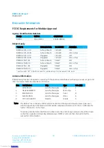
Страница 40: ...ify proper loading of the firmware Because v2 6 and forward requires the firmware to be loaded via multiple images this command verifies that all pages have been upgraded Should an error be encountered the first page encountered that is out of date is reported in the response Command 0xCC 0x00 0x02 Response 0xCC 0x02 Error Page Parameter Range Error 0x00 success 0x09 firmware not complete Page 0x0...

Страница 41: ... according to the selected RF Profile RSSI_1 How strongly the remote radio heard the local radio s bin request RSSI_2 How strongly the local radio heard the remote radio s response Command Descriptions Read Temperature The OEM host issues this command to read the onboard temperature sensor Note The temperature sensor is uncalibrated and has a tolerance of 3ºC For calibration instructions contact L...

Страница 42: ...meters are the same as for the EEPROM parameters Available locations in IRAM are Name Address Range Refresh 0x3D RF Channel 0x41 Interface Timeout 0x58 RF Packet Size 0x5A CTS_On_H 0x5C CTS_On_L 0x5D CTS_Off_H 0x5E CTS_Off_L 0x5F Max Power 0x63 Destination MAC Address 3 0x72 Destination MAC Address 2 0x73 Destination MAC Address 1 0x74 Destination MAC Address 0 0x75 System ID 0x76 Downloaded from ...

Страница 43: ...ress 0 0x75 System ID 0x76 Command 0xCC 0x0B Location Value Number of Bytes Returned 3 Response 0xCC Location Value Parameter Range Location Dependant of parameter Value 0x00 0xFF Downloaded from Arrow com Downloaded from Arrow com Downloaded from Arrow com Downloaded from Arrow com Downloaded from Arrow com Downloaded from Arrow com Downloaded from Arrow com Downloaded from Arrow com Downloaded f...

Страница 44: ...Modification of Auto Destination bit 3 Ignored bit 2 Ignored bit 1 Auto Channel bit 0 Auto Destination Read API Control The OEM host issues this command to read the API Control byte Command 0xCC 0x16 Number of Bytes Returned 2 Response 0xCC API Control Parameter Range Auto Dest bits 7 3 0 bit 2 Send Data Complete bit 1 Transmit API bit 0 Receive API Downloaded from Arrow com Downloaded from Arrow ...

Страница 45: ...ere the ADC result equals the reference voltage and 2048 equals the negative of the reference voltage The ADC cannot measure a voltage higher than the reference voltage Command 0xCC 0x21 Data Number of Bytes Returned 3 Response 0xCC Hi ADC Lo ADC Parameter Range Data bits 7 6 Reference Voltage 00 Internal 1 25V reference 10 Voltage on Vcc pin Data bits 5 4 Resolution 00 64 decimation rate 7 bits r...

Страница 46: ...tes Returned 2 Response 0xCC 0x24 Parameter Range PWM Ratio 0x00 0xFF the ratio of the high pulse versus the Low pulse for a single period Set Max Power The OEM host issues this command to adjust the maximum output power Max Power settings are typical and can vary by 2 dBm The maximum output power never exceeds 18 dBm for RM024 x50 x or 21dBm for RM024 x125 x Command 0xCC 0x25 Max Pwr Number of By...

Страница 47: ...read back for security purposes Radios with the Vendor ID set only communicate to other radios that have Vendor ID set to the same value Once the Vendor ID is set it cannot be changed Setting this value incorrectly results in a radio which is not able to communicate with other radios on the network Setting the Vendor ID is not necessary for the radios to operate and care should be taken when using...

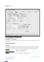
Страница 48: ...e port doesn t appear click Add Ports to add the port manually then repeat step 2 3 Set the correct settings for the radio in Port 1 By default this is 115 200 8 N 1 with Hardware Handshaking enabled 4 Verify that the Port Status in Port 1 is Open 5 In the Radio Firmware Upgrade box select Firmware Upgrade 6 In the Open File Window select the appropriate RM024 FW binaries 7 When the download is su...

Страница 49: ...rrow com Downloaded from Arrow com Downloaded from Arrow com Downloaded from Arrow com Downloaded from Arrow com Downloaded from Arrow com Downloaded from Arrow com Downloaded from Arrow com Downloaded from Arrow com Downloaded from Arrow com Downloaded from Arrow com Downloaded from Arrow com Downloaded from Arrow com Downloaded from Arrow com Downloaded from Arrow com Downloaded from Arrow com D...

Страница 50: ...d is used to read the encrypted image of the flash that resides on the radio module If the image has already been decrypted then this command reports an error Note The length of this command is dictated by the dynamic memory heap If the heap is mostly free then a length of up to 700 bytes could be accepted However if the heap is full the command returns with an error or possibly no response at all...

Страница 51: ...of data Verify Read response is the same data that was written Increment start position Verify length Repeat steps a f until entire image has been loaded 4 Decrypt the FW image Command 0xCC 0xC5 Response 0xCC 0xC5 0x00 5 Reset the radio to begin using the new FW image Command 0xCC 0xFF 6 Repeat steps 2 5 for each binary file Downloaded from Arrow com Downloaded from Arrow com Downloaded from Arrow...

Страница 52: ...Format API Receive Packet By default the source MAC is not included in the received data string sent to the OEM Host For applications where multiple radios are sending data it may be necessary to determine the origin of a specific data packet When API Receive Packet is enabled all packets received by the transceiver include the MAC address of the source radio as well as an RSSI indicator which can...

Страница 53: ...d from Arrow com Downloaded from Arrow com Downloaded from Arrow com Downloaded from Arrow com Downloaded from Arrow com Downloaded from Arrow com Downloaded from Arrow com Downloaded from Arrow com Downloaded from Arrow com Downloaded from Arrow com Downloaded from Arrow com Downloaded from Arrow com Downloaded from Arrow com Downloaded from Arrow com Downloaded from Arrow com Downloaded from Arr...

Страница 54: ...Downloaded from Arrow com Downloaded from Arrow com Downloaded from Arrow com Downloaded from Arrow com Downloaded from Arrow com Downloaded from Arrow com Downloaded from Arrow com Downloaded from Arrow com Downloaded from Arrow com Downloaded from Arrow com Downloaded from Arrow com Downloaded from Arrow com Downloaded from Arrow com Downloaded from Arrow com Downloaded from Arrow com Downloaded...

Страница 55: ...rom Arrow com Downloaded from Arrow com Downloaded from Arrow com Downloaded from Arrow com Downloaded from Arrow com Downloaded from Arrow com Downloaded from Arrow com Downloaded from Arrow com Downloaded from Arrow com Downloaded from Arrow com Downloaded from Arrow com Downloaded from Arrow com Downloaded from Arrow com Downloaded from Arrow com Downloaded from Arrow com Downloaded from Arrow ...

Страница 56: ...ed from Arrow com Downloaded from Arrow com Downloaded from Arrow com Downloaded from Arrow com Downloaded from Arrow com Downloaded from Arrow com Downloaded from Arrow com Downloaded from Arrow com Downloaded from Arrow com Downloaded from Arrow com Downloaded from Arrow com Downloaded from Arrow com Downloaded from Arrow com Downloaded from Arrow com Downloaded from Arrow com Downloaded from Ar...

Страница 57: ...25 M 01 radios FCC IC DVK RM024 P50 C Full Development Kit with one USB Eval Board and one RS 232 Eval Board containing the RM024 P50 C 01 radios FCC IC CE Japan DVK RM024 P50 M Full Development Kit with one USB Eval Board and one RS 232 Eval Board containing the RM024 P50 M 01 radios FCC IC CE Japan Downloaded from Arrow com Downloaded from Arrow com Downloaded from Arrow com Downloaded from Arro...

Страница 58: ...e antenna type and gain should be chosen so that the equivalent isotropically radiated power EIRP is not more than that permitted for successful communication Downloaded from Arrow com Downloaded from Arrow com Downloaded from Arrow com Downloaded from Arrow com Downloaded from Arrow com Downloaded from Arrow com Downloaded from Arrow com Downloaded from Arrow com Downloaded from Arrow com Downloa...

Страница 59: ...el However the type size for the text is not required to be larger than eight pt CAUTION The OEM should have their device which incorporates the RM024 tested by a qualified test house to verify compliance with FCC Part 15 Subpart B limits for unintentional radiators WARNING This device has been tested with an U FL connector and the antennas listed in the table above When integrated into the OEM s ...

Страница 60: ...ove are approved for use in CE Markets with antennas having a maximum gain of 2 5 dBi Antennas having a gain greater than the maximum allowed are strictly prohibited for use with this device The required antenna impedance is 50 Ohms CE Tested Antenna List Laird Part Manufacturer Part Manufacturer Type Gain dBi WIC2450 A Laird Technologies Chip 2 0600 00040 S181 6 PX 2450S Nearson Dipole 2 WCP2400 ...

Страница 61: ...l Release Downloaded from Arrow com Downloaded from Arrow com Downloaded from Arrow com Downloaded from Arrow com Downloaded from Arrow com Downloaded from Arrow com Downloaded from Arrow com Downloaded from Arrow com Downloaded from Arrow com Downloaded from Arrow com Downloaded from Arrow com Downloaded from Arrow com Downloaded from Arrow com Downloaded from Arrow com Downloaded from Arrow com ...

Страница 62: ...M2 the intent is that the Client should be able to sleep for tens of minutes and maintain frequency hop synchronization with the Server when it wakes Currently PM2 is using a static calibration that permits the Client to maintain synchronization with the Server for roughly 2 minutes Future releases will include a dynamic unobtrusive calibration algorithm to permit much longer PM2 times while succe...

Отзывы: