RM024 User Manual
Version 2.3
Americas: +1-800-492-2320 Option 2
Europe: +44-1628-858-940
Hong Kong: +852-2923-0610
www.lairdtech.com/wireless
60
CONN-GUIDE-RAMP24-0413
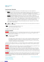
CAUTION:
Any changes or modifications not expressly approved by Laird Technology could void the user’s
authority to operate the equipment.
NOTE: This equipment has been tested and found to comply with the limits for a Class B digital device,
pursuant to Part 15 of the FCC Rules. These limits are designed to provide reasonable protection
against harmful interference in a residential installation. This equipment generates, uses, and can
radiate radio frequency energy and, if not installed and used in accordance with the instructions,
may cause harmful interference to radio communications. However, there is no guarantee that
interference will not occur in a particular installation. If this equipment does not cause harmful
interference to radio or television reception, which can be determined by turning the equipment off
and on, the user is encouraged to correct the interference by one or more of the following measures:
Re-orient or relocate the receiving antenna
Increase the separation between the equipment and the receiver
Connect the equipment to an outlet on a circuit that is different from that to which the
receiver is connected.
Consult the dealer or an experienced radio/TV technician for help.
CAUTION:
“THIS DEVICE COMPLIES WITH PART 15 OF THE FCC RULES AND INDUSTRY CANADA LICENSE-EXEMPT RSS
STANDARD(S). OPERATION IS SUBJECT TO THE FOLLOWING TWO CONDITIONS: (1) THIS DEVICE MAY NOT CAUSE
HARMFUL INTERFERENCE, AND (2) THIS DEVICE MUST ACCEPT ANY INTERFERENCE RECEIVED, INCLUDING
INTERFERENCE THAT MAY CAUSE UNDESIRED OPERATION.
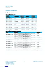
CE Requirements for Modular Approval
RM024 Part Numbers approved for CE
*PART #
FORM FACTOR
TX OUTPUT
ANTENNA
RM024-S50-C-XX
Surface Mount
50mW
U.FL
RM024-S50-M-XX
Surface Mount
50mW
U.FL or chip
RM024-P50-C-XX
Pluggable
50mW
U.FL
RM024-P50-M-XX
Pluggable
50mW
U.FL or chip
*Last two slots "XX" in Part # are used for custom setups. Can be values 01-99, aa-zz
Part Numbers listed above are approved for use in CE Markets with antennas having a maximum gain of 2.5
dBi. Antennas having a gain greater than the maximum allowed are strictly prohibited for use with this
device. The required antenna impedance is 50 Ohms.
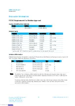
CE Tested Antenna List
Laird Part #
Manufacturer Part #
Manufacturer
Type
Gain (dBi)
WIC2450-A
Laird Technologies
Chip
2
0600-00040
S181-6-PX-2450S
Nearson
Dipole
2
WCP2400
Laird Technologies
Dipole
2
2150-00006
NZH2400-MMCX
Laird Technologies
Dipole
1
Note: The OEM is free to choose another vendor’s antenna of like type and equal or lesser gain as an
antenna appearing in the table and still maintain compliance. Antennas listed in this table have
been test with the RM024
Downloaded from
Downloaded from
Downloaded from
Downloaded from
Downloaded from
Downloaded from
Downloaded from
Downloaded from
Downloaded from
Downloaded from
Downloaded from
Downloaded from
Downloaded from
Downloaded from
Downloaded from
Downloaded from
Downloaded from
Downloaded from
Downloaded from
Downloaded from
Downloaded from
Downloaded from
Downloaded from
Downloaded from
Downloaded from
Downloaded from
Downloaded from
Downloaded from
Downloaded from
Downloaded from
Downloaded from
Downloaded from
Downloaded from
Downloaded from
Downloaded from
Downloaded from
Downloaded from
Downloaded from
Downloaded from
Downloaded from
Downloaded from
Downloaded from
Downloaded from
Downloaded from
Downloaded from
Downloaded from
Downloaded from
Downloaded from
Downloaded from
Downloaded from
Downloaded from
Downloaded from
Downloaded from
Downloaded from
Downloaded from
Downloaded from
Downloaded from
Downloaded from
Downloaded from
Downloaded from


