-7-
www.igmtools.com
6.2 Installing/Removing Faceplate & Hand Wheel
WARNING!
Unplug the machine from power source!
TIP
Do not over torque the threading, only firm pressure is required.
TIP
Remove set screws prior to removing faceplate. The screws are
located on the flat part of the spindle. Do not disassemble by force.
Remove screws completely or you can damage the spindle.
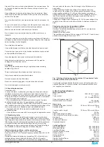
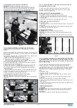
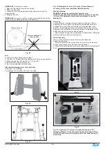
Fig. 11
Fig. 11: Faceplate installation. (1) Spindle Lock. (2) Faceplate
wrenching hole. (3) Knockout rod or Faceplate wrench. (4) Set
screws.
Simply screw the faceplate intro the spindle threading. The spindle is with
M33 x 3,5 mm right hand threads. There is a cutting slot on the spindle for
the set screws.
Tools needed: Faceplate wrench (PLAREVO1836-1136) or Knockout rod
(PLAREVO1216-1103A) and 3mm Hex wrench
1. Make sure the lathe is unplugged and cannot be turned on.
2. Position the banjo out of the way to prevent damage.
3. Check that the set screws (Key 4) are not engaged. Remove all set
screws that are tightened down with Hex wrench.
4. Press the spindle lock (Key 1) inward to lock the spindle. Rotate the
spindle a bit to line it up with the pin hole.
5. With spindle lock (Key 1) engaged and set screws removed, fit the
faceplate wrench (Key 3) into the faceplate wrenching hole (Key 2).
6. Turn counter clock-wise to remove the faceplate, turn clock-wise to
install the faceplate.
7. When installing, reverse these steps. TIP The faceplate wrench is not
needed for the assembly. If you over-tighten the set screws you could
damage the threading. Hand tightening is enough.
6.3 Installing/Removing Drive Centre and Live Centre
Warning!
Unplug the machine from power source!
TIP
Do not attempt to remove the live centre with tools, turn the quill until
it pops out.
TIP
The centres pop out quickly, prevent from dropping.
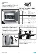
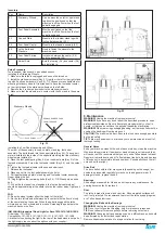
Fig. 12
Fig. 12 - Centre Installation. (1) Knockout rod. (2) Drive Centre. (3)
Quill Hand Wheel. (4) Live Centre.
To install the centres, simply press them into the boring. When the
workpiece is loaded both centres will be pressed into a firm position.
Methods of centre installation vary.
6.4 Removing Drive Centre from Headstock
Tools needed: Knockout rod (PLAREVO1216-1103A).
1. Make sure the lathe is unplugged and cannot be turned on.
2. Lightly grasp the drive centre with free hand prior to step 3 - it will pop
out unexpectedly.
3. Use the knockout rod (Key 1) and lightly tap on the centre.
6.5 Removing Live Centre from Tailstock
Tools needed: none
1. Lightly grasp the live centre with free hand prior to step 2 - it will pop out
unexpectedly.
2. Turning the quill hand wheel (Key 3) counterclockwise will retract quill
and release the live centre from the quill.
6.6 Changing Speed Range
WARNING!
Unplug the machine from power source!
CAUTION!
Pinching hazard. Do no rotate the spindle with hands in the
belt cabinet.
TIP
Do not attempt any other pulley configurations than those described
below.
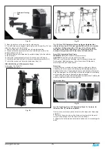
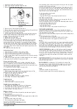
Fig. 13
Fig. 13: Changing Speed Range. (1) Low Speed Range: 50-525 RPM.
(2) Mid Speed Range: 325-1750 RPM. (3) High Speed Range: 650-3500
RPM. (4) Belt Tension Cam Handle. (5) Drive Pulley. (6) Groove Poly-V
Belt. (7) Driven Pulley.
The lathe has three sets of pulleys for high, medium, and low speed
as described above. The belt should be tensioned so that there is
approximately 3 to 6 mm (1/8 to 1/4“) deflection when the belt is pressed
with moderate thumb pressure. To adjust the amount of tension, see the
Adjustment section. To adjust between the speed ranges, follow these
steps:
Tools needed: none
Unplug the machine from power source!
2. Open both pulley covers to access upper (Key 7) and lower (Key 5)
pulleys.
3. To loosen the belt tension, turn the belt tension cam handle (Key 4)
towards you.
4. Move the drive belt (Key 6) to the required set of pulleys.
5. Tension the belt by returning the belt tension cam handle (Key 4) to its
original position.
6. Test that the belt is set correctly by manually turning the spindle prior to
returning power to the lathe.
7. Machine Operation
7.1 First Use
WARNING!
Read the entire owners manual prior to using this machine.
WARNING!
Never load or adjust the workpiece while the machine is
switched on.
CAUTION!
The workpiece must be balanced to limit vibrations.


