-11-
www.igmtools.com
Inventory
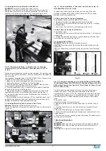
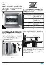
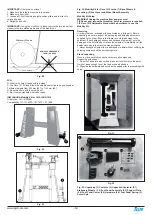
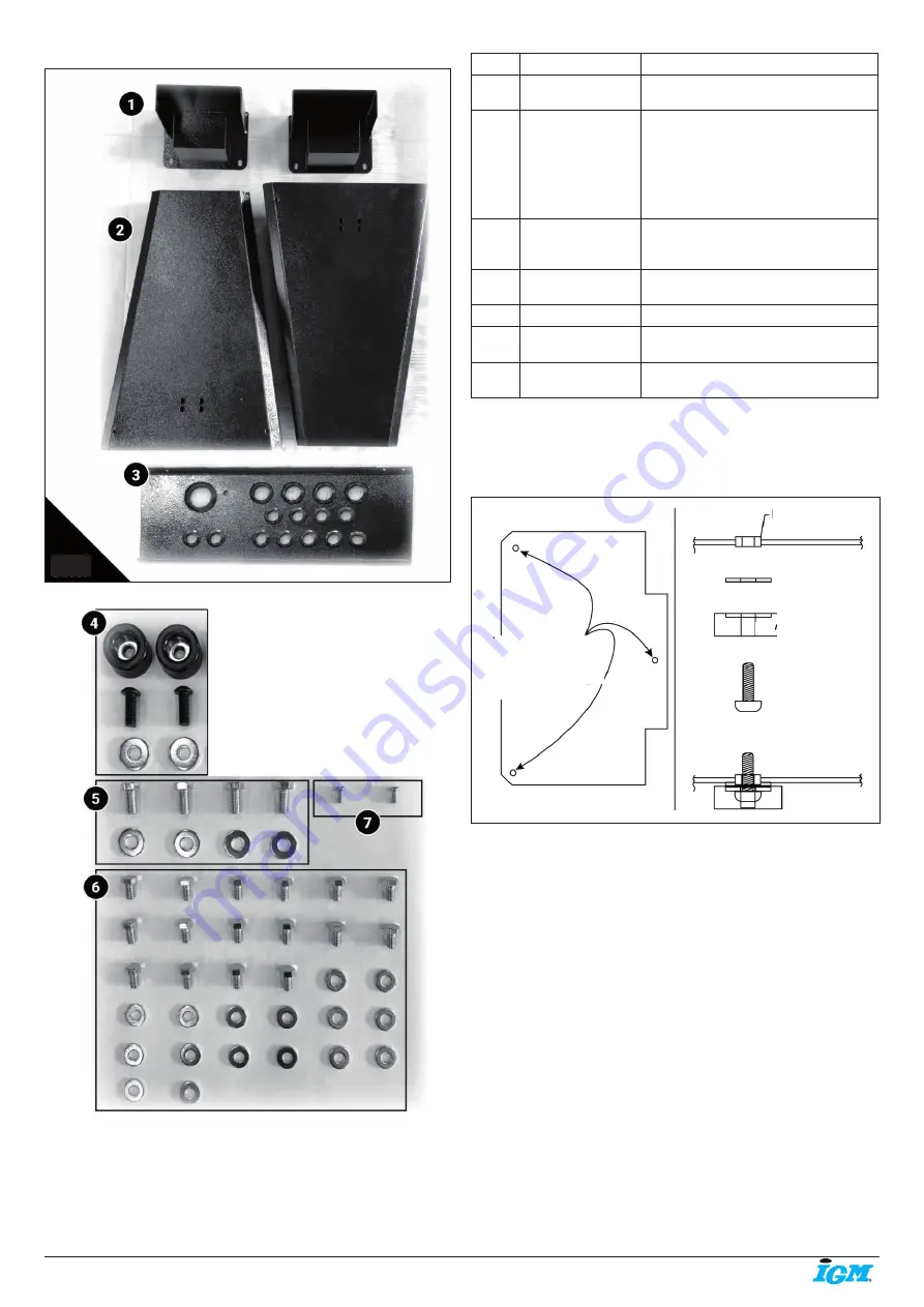
Fig. 25
Fig. 26
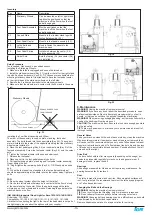
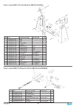
Fig. 26: Revo 1216 Adjustable Stand Inventory.
(1) Adjustable height pillars. (2) Stand Leg. (3) Tool Rack. (4) Rubber
pads, screws and washers. (5) Lathe attachment bolts and washers.
(6) Bolts and washers for assembly. (7) Height constraint screws.
Key
Name
Description
1
Height Pillar
PLAREVO1216-204
Main contact point from lathe to stand.
Allows for adjustable height.
2
Stand Leg
PLAREVO1216-201
PLAREVO1216-202
Sheet Steel constructed stand leg. Has
pre-tapped holes to mount.
TECH TIP
These legs are not the same. You will
notice that the bolt holes that connect
the organization shelf are not at the
same height. The lower positioned bolts
holes must be front.
3
Organization Shelf
PLAREVO1216-203
Adds structural stability to stand. Also
holds 13 turning chisels/tools and all
functional set-up tools.
4
Rubber Pads
/Bolts/Washer
Used on the bottom of the stand legs to
minimize vibration.
5
Lathe Bolts/Washer Lathe to stand Fasteners.
6
Assembly
Hardware
Height adjustment fasteners, shelf to leg
fasteners,
7
Height Constraint
Screw
Positions maximum height of
lathe stand.
Setup Procedure
1. Make sure the lathe is unplugged and cannot be turned on.
2. Remove the rubber pads from the lathe. This will give 6 rubber pads, 6
hex bolts and 6 washers.
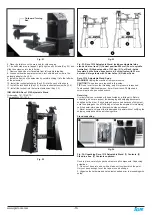
3. Install the rubber pads (Key 4) to the stand legs (Key 2) with Hex
screws and washers.
Fig. 27
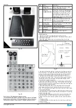
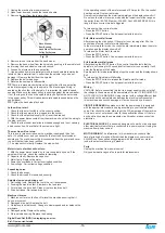
4. Identify the left and the right leg. There are four bolt holes on each leg
for the rack (Key 3). The upper two bolt holes must face the rear of the
machine, the lower two bolt holes must face the front of the workspace.
The rack is then installed so that is it angled towards the operator.
5. Identify the correct orientation of the tool rack (Key 3). The lip of the
rack should not be visible. In Fig. 17 the shelf is upside down. A properly
installed rack should have the largest hole (faceplate storage) on the
furthest left and towards the operator.
6. Fasten the stand legs to the tool rack. Use 8 bolts and washers (Key 6).
Tighten all screws at the end of the setup. TIP The stand will not be rigid
until it is fastened to the lathe. Once the lathe is attached and the height is
adjusted properly, it will be very rigid.
7. Install the height pillars (Key 1) to the stand legs with the remaining
eight bolts and washers (Key 6). Tighten all screws at the end of the
setup. TIP Assuming the final height now is easier than later. Nevertheless
it can be positioned later.
8. Carefully reach into the stand leg and install the height constraint screw
on each pillar (Key 7). These screws will prevent the operator from pulling
the lathe out of the stand.
9. Using an additional person, place the lathe onto the stand. Attach the
lathe to the stand. CAUTION! One person must focus on holding the
position of the lathe while the other positions the four bolts and washers
(Key 5).
10. Tighten all bolts.
11. For safety, remove the lathe away from the stand if you would like to
change the height.
12. Avoid over tightening.
Three Rubber
Pads location.
Hex Bolt
Washer
Pre-
Threadings
Rubber Pad (with
pre-installed
washer)


