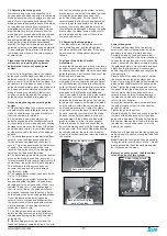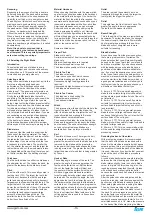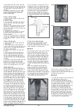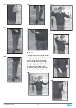
-11-
www.igmtools.com
7.5 Adjusting the blade guards
Welcome to a new era in bandsawing. You
have purchased a bandsaw with a revolutionary
blade guide system that is designed to give you
years of safe, high-quality bandsawing. Most
blade guides are designed to support the blade
on the sides and either above or below the
side guides at the back of the blade. This can
allow the blade to twist as pressure from the
wood being cut pushes against the back blade
guide. The Laguna Guide eliminates this by
supporting the blade above and below the back
blade guide, giving the blade unsurpassed
stability. The Laguna Guide also incorporates
patented ceramic as the blade support material.
The advantage of this material is its ability to
resist wear, and with care it should give years
of safe service.
Please read the following notes as they
will assist you in getting the optimum
performance from your Laguna guide
system.
As with the roller guide systems, the Laguna
guide system will damage your blade if it is not
adjusted correctly. The guide blocks must not
come in contact with the teeth of the blade. It is
advisable to run the blade by hand with the
guide blocks completely clear of the blade, and
only when you are completely sure that the
blade is running consistently in the correct
position, you may then adjust the surround
guide blocks as detailed in this manual.
Note on using the Laguna ceramic guide
system.
1.
When fitting a blade to your bandsaw, adjust
the guide blocks as detailed later and run the
blade by hand through the guide blocks for at
least two complete revolutions.
2.
The weld on a new blade may not be
perfectly aligned, and the misalignment could
hit the ceramic blocks (side and back), causing
damage to the blocks or the blade. If the blade
has a bad weld, return it to your blade supplier
or side dress and file the back of the blade as
needed.
3.
The back blade guide is manufactured from
ceramic, so as the blade pushes against it,
friction between the blade and the ceramic
occurs. This action generates a certain amount
of sparks. This is normal and will become
less with time as the back of the blade guide
smoothes out the back of the blade.
4.
The back blade guide will slowly form a small
grove as the blade is used (this is normal). It
is recommended that for approximately every 8
hours of use, the guide be rotated 15 degrees.
This will ensure that the groove does not
become too deep and will greatly extend
the life of your guide.
5.
The Laguna guide system can be used with
1/8” to 1-1/4”blades.
6.
The Laguna guide system uses ceramic to
support and guide the blade. This has many
advantages (very poor conductor of heat, very
resistant to wear, etc.). The disadvantage is
that it is very brittle, so the guides must never
be dropped, exposed to hard knocks, hit with
hard objects or used with badly welded blades.
Any of the above actions may cause the
ceramic to chip or break and will detract from
the performance of the Laguna guide system.
Any mistreatment of the guide system will
render the warranty void.
7.
The side guide blocks must be tightened
before running the machine to avoid jamming
the blade and damaging the machine and/or
guide blocks.
8.
When cutting gummy or green wood, the
blade can become covered with resin. You will
find that the surround guide system ceramic
blocks remove the resin as the blade is moved
through the guide blocks and keep that
part of the blade clean. For this reason it is
recommended that the blocks be adjusted as
close to the gullet as possible, but the teeth
must not come in contact with the blocks, as
they will become damaged. Although the guide
blocks clean the blade, some woods will still
gum the blade and the resin will have to be
removed with solvent.
7.6 Adjusting the blade guides
The blade should run through the center of
the rear blade guide, and the side guides
should be parallel with the blade. If they have
been moved out of adjustment, adjust as
follows:
Top Upper Side Guides Parallel
Adjustment.
Loosen the side guides and move out as far as
possible. Loosen the guide assembly and move
back away from the blade. Move the back blade
guide forward so it just touches the back of the
blade and lock in position.
Loosen the guide clamp screw that allows the
side guides to move forward and back. Adjust
so that the ceramic blocks are just behind the
gullet of the teeth and are parallel to the blade.
Retighten the clamp screws. Gently push one
side guide so that it touches the blade and
lock it in position. Bring the other guide toward
the blade so that there is minimal clearance
between the blade and the guide. You can put
a thin piece of paper to put between the blade
and the guide to obtain the correct clearance
until you gain experience. Tighten the clamp
screws and remove the paper. Rotate the blade
by hand, ensuring that the weld of the blade
does not hit the ceramic blocks, as this will
cause damage. If the blade has a bad weld,
dress the blade or return it to your supplier.
Rotate the blade by hand and check that the
back of the blade does not hit the blade guide
with a bad weld. If the back of the blade hits the
back blade guide at the weld, then dress the
blade or, in excessive cases, return the blade to
the supplier.
Lower blade guide.
The lower blade guides have two locking
screws that, when released, allow the guide
assembly to be moved forward and back.
Rotate the blade by hand and ensure that it
is tracking consistently in the correct position.
Loosen the side guides and move out from the
blade. Loosen the two clamp screws that allow
the guide assembly to move forward and back.
Adjust it so that the ceramic blocks are just
behind the gullet of the blade and retighten the
clamp screws.
Place a dollar bill or piece of paper of similar
thickness between the guide blocks and the
blade. Gently bring both side guides toward the
blade so that slight pressure is exerted on the
blade. Tighten the clamp screws and remove
the paper. Rotate the blade by hand, ensuring
that the weld of the blade does not hit the
ceramic blocks, as this will cause damage. If
the blade has a bad weld, dress the blade or
return it to your supplier.
Loosen the rear guide clamp screw and push
the guide forward so that it just touches the
back of the blade.
Tighten the guide in position.
Rotate the blade by hand and check to see that
the back of the blade does not hit the blade
guide with a bad weld. If the back of the blade
hits the rear blade guide at the weld, then dress
the blade or, in excessive cases, return the
blade to the supplier.
Note:
You will probably find that the guides can
be adjusted more easily by tilting the table to 45
degrees.
Note:
Rotate the back guide by approximately
15 degrees after every 8 hours of use. This will
greatly extend the life of the back blade guide,
as it will even out the wear.
Before you cut any wood, read the safety
rules at the front of this manual.
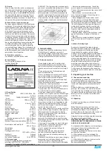
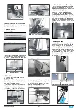
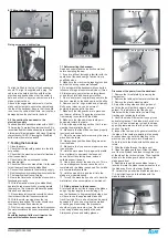
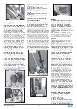
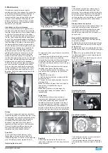
Side guide clamp screw
Back guide clamp screw
Back guide touching the
back of the blade
Adjusted guide
Guide locking screws


