© copyright 2005
(P/N)12-249 v2 • 9/08
Kaba Mas LLC
page 7 of 8
TIME LOCK SET-UP EXAMPLES
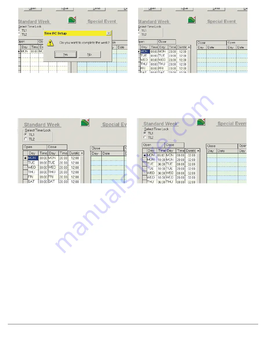
• Lock available 7 days a week during business hours - in this case business hours are 8am to 8pm 7 days a week. (see Screen 20).
• Lock available 6 days a week during business hours - in this case business hours are 8am to 8pm 6 days a week, closed on Sunday (see
Screen 21).
• Lock set for multiple time lock periods in one day. Set for 5 days, closed Saturday and Sunday (see Screen 22).
SENDING TIME LOCK SET-UP TO THE LOGIC MODULE
This function requires the use of the Logic Module Programming Cable (P/N 43097) and a Serial Interface Connector.
1. Connect power to the Logic Module. (Requires the use of a 9V battery.) Duracell
TM
or Eveready
TM
batteries are recommended.
2. Plug Interface and cable into PC and open SMARTLINC Set-up software.
3. Connect the 43097 cable to the Logic Module through the port on the keypad.
4. Open the correct file for the Time Lock period (1 or 2) that will be downloaded to this lock.
5. Press the Send button on the software (see Screen 23).
• The software will instruct you to activate the PC Link in the Master Menu on the Logic Module (see Screens 23 & 24).
6. Press any key to power up SMARTLINC.
• Display will show either “ENTER COMBO” or SELECT LOCK” when two or more locks are installed.
7. Hold down “zero” until the display shows “MASTER, X-X-X-X-X-X-X-X”
8. Enter the MASTER code.
9. Press the “P” button four (4) times to select PC Link; the display will show “PC LINK”. Press OK to start communication with the PC.
10. On the screen the software will scroll through each Record number as it downloads, then it will show OK.
• In order to exit from PC Link, press the “P” button three (3) times. When the screen reads “Do you want to QUIT?”, press the “OK”
button to exit.
NOTE: If the computer does not have a serial port, a serial to USB connector will be required.
Screen 19
Screen 21
Screen 20
Screen 22


