© copyright 2005
(P/N)12-249 v2 • 9/08
Kaba Mas LLC
page 4 of 8
CONTROL UNIT (LOGIC MODULE) SET-UP
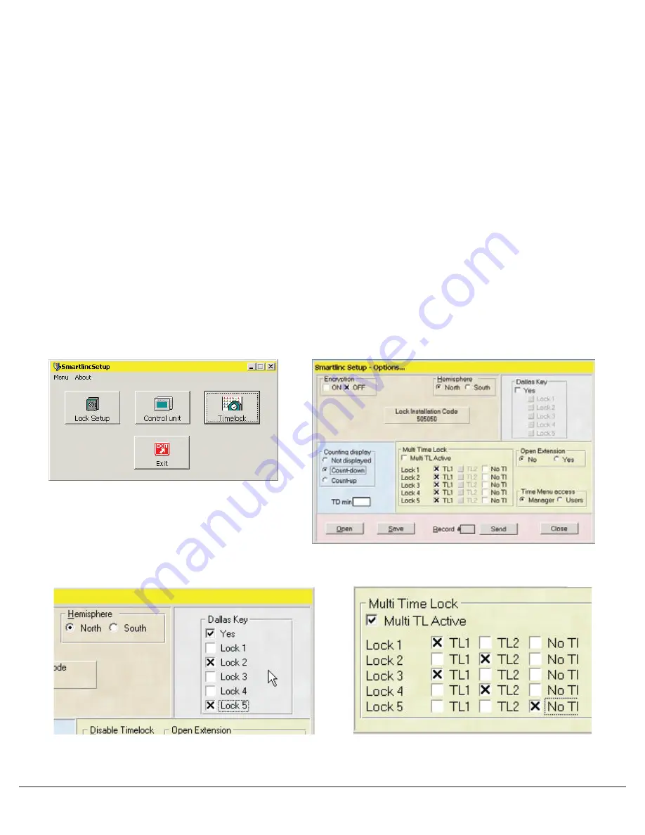
To set up the logic module, click on the Control Unit Set-up button on the opening screen (see Screen 8). A window with the default
configuration will appear (see screen 9). In this window select the features to be enabled on the Logic Module.
• Encryption can be set either ON or OFF. The default is set for OFF.
CAUTION: If encryption is set ON, once the locks have been installed to this Logic Module, this will be the only Logic Module able to
be used with these locks.
• Hemisphere is set with a default for NORTH. Select the Hemisphere where the units will be active.
• The Dallas
®
key (eKEY
II
) option can be selected on this page. Check the YES box, then select which locks to set up for use with eKEY
II
,
(see Screen 10).
• Delay Counting Display is set to a default of Countdown. Available options are to have Time Delay counting sequence Count Up,
Count Down or Not Displayed.
• The TD MIN window allows the entry of a minimum Time Delay value. Once this number is entered, Managers having access to the time
menu will not be able to change the Time Delay value below this minimum delay period number. This feature will program ALL locks on
the system that have a Time Delay set-up.
• Multiple Time Lock periods are available by checking the box marked Multi TL Active (see screen 11). If there is no check in the Multi TL
Active box, any time lock periods programmed will apply to all locks enrolled in the system. For a different Time Lock period to apply to
a specific lock, check the Multi TL Active box. The locks enrolled in the system may be set to Time Lock period 1, 2 or No Time Lock.
• Open Extension is set to NO by default. With this option, no one will have access to the Open Extension Time Menu on the Logic
Module. Selecting YES allows the Manager and/or Users (as selected in the next option) to access the Time Lock Open Extension menu
on the Logic Module. Those who have access can then extend the Time Lock Open Period in 30 minute increments, but no more than
two hours or four (4) 30 minute increments.
• Time Menu Access allows you to select whether both the Manager and the Users or the Manager only will have access to the
Time Menu.
• The Lock Installation Code (5-0-5-0-5-0) is used to enroll the locks to the Logic Module during System Set-up using the Master Menu on
the Logic Module.
Once all of the features for this lock have been selected, save the set-up to a file for later use. If a file has already been saved, it may be
opened from this window as well.
Screen 8
Screen 10
Screen 11
Screen 9


