With the help of a special mandrel (like a screwdriver) take
out the input shaft together with the bearing and the synchro unit
ring (fig. 3-28) and remove the needle bearing from the front end
of the output shaft.
Punch out the output shaft from the idler bearing, take out the
idler bearing and, having inclined as shown on fig. 3-29, take out
from the crankcase the output shaft in assembly with gears, cou-
plings and synchro unit rings. Remove the 3rd/4th synchro unit
sleeve from the shaft.
Dismantle the input shaft (fig. 3-30):
- remove circlip 7, baulk ring 6 and spring 5;
- place the shaft on a press and, having fixed the spring
washer 2 with tool 41.7816.4069, remove circlip 1, and then the
spring washer and bearing 3.
Dismantle the output shaft (fig. 3-31):
- from the rear end of the shaft remove the 1st synchro gear
11 with bush 12, hub 3 with 1st/2nd synchro sleeve 4, 2nd speed
gear 10 together with baulk ring 5;
- place the output shaft with tool 41.7816.4069 on a press (fig.
3-32), place two thrust half-rings 3 under 3rd speed gear and by
pressing the spring washer with the mandrel, remove the circlip 2,
then spring washer 4, 3rd/4th sleeve hub and 3rd speed gear.
If necessary, dismantle the lever and the gear selector mech-
anism. Proceed as follows:
- take off rubber boot 10 (fig. 3-33), thrust ring 6 and circlip 7,
spring 5 and cap 4 from the gearshift lever;
70
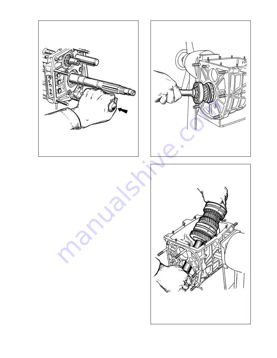
Fig. 3-29. Withdrawing the output shaft from the transmission casing
Fig. 3-27. Undoing the fastening bolts of the output shaft idler gear plate
with an impact screwdriver.
The arrow shows the direction of the screwdriver thrust stroke when striking with
a hammer
Fig. 3-28. Withdrawing the input shaft from the transmission casing
Содержание Niva 4x4
Страница 80: ...135 ...
Страница 81: ...136 ...


