Master and slave cylinders -
dismantling, inspection, repair and reassembly
Master cylinder.
Turn out plug 3 (fig. 3-8), remove protective
rubber cap 7 and circlip 8. This will allow to withdraw from the
cylinder body piston 9, sealing ring 10, floating piston 11 with
sealing ring and piston return spring 12.
Cylinder mirror and the outer surface of the piston should
have no damages or marks. The inner diameter of the cylinder
should be within the limits of 19.035-19.075 mm.
Inspect the piston return spring and replace if it has become
weak.
Renew sealing rings. Inspect the protective cap on the rear
end of the cylinder and renew in case of damage. Before reas-
sembly, accurately clean and wash all parts in brake liquid. Do
not let mineral oil, petrol, kerosine or diesel fuel to get in contact
with the parts as this may cause swelling of the rubber sealings.
After inspection, reassemble all parts of the master cylinder
in reverse order; grease all components with brake liquid or
preservation liquid çÉ-213.
Slave cylinder.
Turn out plug, take off protective rubber cap
3 (fig. 3-9) together with pushrod 4, take out piston and disman-
tle it, previously having removed lock ring 11.
After dismantle, accurately wash and check all parts, as it is
specified for the master cylinder. Do not refit a damaged
pushrod.
After inspection, begin to reassemble in reverse order,
grease all parts with brake liquid.
Clutch master cylinder - bench-check
Checking the leak-proofness of the rear sealing ring
.
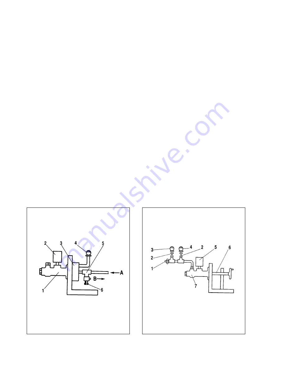
Place the master cylinder on the test-bench (see fig. 3-10), and
ensure good sealing between the cylinder flange and the surface
of the test-bench. Connect reservoir 2 with hydraulic liquid to the
cylinder. Open the compressed air vent, with the adjusting screw
6 being open, and then slowly close the adjusting screw until all
air will be expelled from reservoir 2.
Control air pressure by the pressure gauge, it should be with-
in 0.05-0.08 MPA (0.5-0.8 kgf/cm
2
). If pressure is less, replace
the rear sealing ring.
Checking the leak-proofness of the front sealing ring.
Place the master cylinder on the test-bench and connect it to the
reservoir with hydro drive liquid, and with manometers (fig. 3-11).
Close manometer vent 3 and, by moving the master cylinder
pushrod, provide constant pressure of 0.2 MPA (2 kgf/cm
2
).
With a fixed pushrod and no liquid leaks pressure should
remain constant during 2 minutes.
Close pressure gauge vent 4 and open pressure gauge vent
3. By moving the pushrod provide constant pressure of 10 MPA
(100 kgf/cm
2
).
With a fixed pushrod and no liquid leaks pressure should
remain constant for no less than 2 minutes. Otherwise, replace
the front sealing ring.
63
Fig. 3-10. Checking the leak-proofness of the rear sealing ring:
1 - master cylinder; 2 - reservoir; 3 - adapter with sealing; 4 - manometer;
5 - T-connector; 6 - adjusting screw; A - air from compressor; B - air outcome
Fig. 3-11. Checking the leak-proofness of the front sealing ring:
1 - bleeding screw; 2 - vent; 3 - manometer with 0.2 MPa (2 kgf/cm
2
) scale;
4 - manometer with 0.005 MPa (0.05 kgf/cm
2
) scale; 5 - reservoir;
6 - pushrod; 7 - master cylinder
Содержание Niva 4x4
Страница 80: ...135 ...
Страница 81: ...136 ...


