background image

OilSET-1000 Oil Separator Alarm Device 


D15492AE-2 

Installation and Operating Instructions


Copyright © 2019 Labkotec Oy 

2/13 

We reserve the right for changes without notice 


TABLE OF CONTENTS 


1


GENERAL ............................................................................................................ 3


2


INSTALLATION ................................................................................................... 4


2.1


OilSET-1000 control unit .............................................................................. 4


2.2


SET/DM3AL sensor ..................................................................................... 5


2.3


Cable joint .................................................................................................... 5


3


OPERATION AND SETTINGS ............................................................................ 6


3.1


Operation ..................................................................................................... 6


3.2


Factory settings ............................................................................................ 7


4


TROUBLE-SHOOTING ....................................................................................... 8


5


REPAIR AND SERVICE ...................................................................................... 9


SAFETY INSTRUCTIONS ........................................................................................ 9


6


TECHNICAL DATA ............................................................................................ 10


DECLARATION OF CONFORMITY ....................................................................... 11


DECLARATION OF CONFORMITY ....................................................................... 12


DECLARATION OF CONFORMITY ....................................................................... 13


SYMBOLS


Warning / Attention 


Pay special attention to installations at explosive atmospheres 


Device is protected by double or reinforced insulation 


Содержание OilSET-1000

Страница 1: ...8 29 006 260 Fax 358 29 006 1260 23 9 2019 Internet www labkotec fi D15492AE 2 1 13 Copyright 2019 Labkotec Oy We reserve the right for changes without notice OilSET 1000 Oil Separator Alarm Device wi...

Страница 2: ...trol unit 4 2 2 SET DM3AL sensor 5 2 3 Cable joint 5 3 OPERATION AND SETTINGS 6 3 1 Operation 6 3 2 Factory settings 7 4 TROUBLE SHOOTING 8 5 REPAIR AND SERVICE 9 SAFETY INSTRUCTIONS 9 6 TECHNICAL DAT...

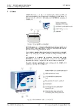
Страница 3: ...is installed into the light liquid storage chamber and gives an alarm when the chamber is filled to a pre determined degree The sensor is normally immersed in water The function is based on the measu...

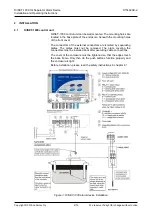
Страница 4: ...re beneath the mounting holes of the front cover The connectors of the external conductors are isolated by separating plates The plates must not be removed The plate covering the connectors must be in...

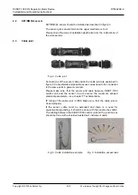
Страница 5: ...ined in figure 3 Cable shields and possible excess wires need to be connected to the same point in galvanic contact Please make sure that the sensor and cable between OilSET 1000 control unit and the...

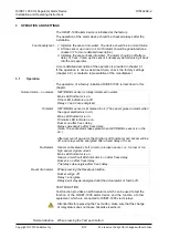
Страница 6: ...LED indicators are off Relays 1 and 2 are energized Oil alarm SET DM3AL sensor is immersed in oil The sensor gives an alarm when the upper electrode is in oil Mains LED indicator is on Oil Alarm LED...

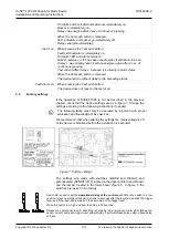
Страница 7: ...OilSET 1000 is not as described in the previous chapter check that the device settings are as in figure 7 Change the settings according to the following instructions if needed The following tasks mus...

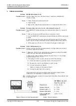
Страница 8: ...ensor should give an alarm again Problem FAULT LED indicator is on Possible reason Current in sensor circuit too low cable break or too high cable in short circuit The sensor might also be broken To d...

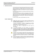
Страница 9: ...tentially explosive atmosphere Sensors connected to it may be installed in zone 0 1 or 2 potentially explosive atmospheres In case of installations in explosive atmospheres the national requirements a...

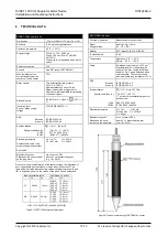
Страница 10: ...e g 19 2019 Due to non linear characteristics of the sensor voltage the interaction of both capacitance and inductance must be taken into account The table below indicates the connecting values in exp...

Страница 11: ...DECLARATION OF CONFORMITY...

Страница 12: ...DECLARATION OF CONFORMITY...

Страница 13: ...DECLARATION OF CONFORMITY...

Отзывы: