background image

32 


4.  Place the cap from step 5 (Figure 4-3) on the connector called out in Figure 4-

(titled “Place cap here”). This is important to protect the filter junction for 

future use. Do not skip this step. 


Step 15


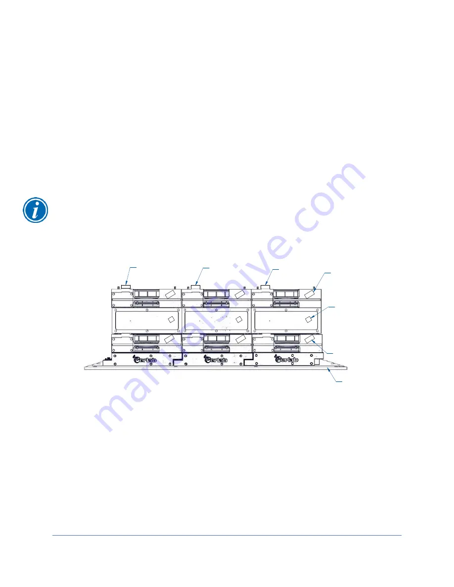
Make sure the secondary filter is properly seated on all sides of the fan box. When all 
secondary filters are in place, use a piece of tape and marker to 

label the filter’s 

position. If the filter is placed in the first column (the one closest to the command 
module) the tape label will sa

y “1S” for 1

st

 column and secondary filter. If the filter is 

above the fan in the 3rd column away from the 

command module, label it “3S”. 


Step 16


Repeat steps 14 & 15 with all the secondary filters needed for your size of filtered hood.


For a 5FT (M3) filtered hood example of what the completed filter installation looks like 
including column labels see Figure 4-9. Your filtered hood should be stacked and 
labeled like Figure 4-9. Caps should be on 

top of all the secondary filter’s connections to 

protect them. The command module side is called out for reference.  

Calibrating the Airflow Sensor 

Airflow sensor calibration is required for safe operation of the filtered hood. The 
calibration is important for the function of the filtered hood and should be repeated 
frequently. An annual calibration is recommended to ensure accuracy while in use. The 
entire process will take about 5 minutes to complete. Always make sure no wiring, 
plumbing or power cords are blocking the inlet of the sensor. 

Always calibrate with 

both side panels installed to prevent cross drafts near the airflow sensor.


Step 1 

Turn the filtered hood on. The lights and fans should be working properly with no errors. 


1 P

2 P

3 P

1 S

2 S

3 S

1

2

3

CAP

CAP

CAP

"1S" LABEL

"1" LABEL

"1P" LABEL

SIDE OF THE
COMMAND MODULE


Figure 4-9 

Содержание Protector Echo

Страница 1: ...ltered Fume Hoods Register this product LABCONCO CORPORATION 8811 Prospect Avenue Kansas City MO 64132 800 821 5525 I 1 816 333 8811 labconco com Please read user s manual before operating equipment O...

Страница 2: ...610xxx 181810xxx 182410xxx 182510xxx 182610xxx 182810xxx Protector Airo Bench Top Filtered Fume Hood 2020 Present 184300xxx 184310xxx 184410xxx Protector Echo Floor Mount Filtered Fume Hood 2020 Prese...

Страница 3: ...s to restore the unit to operation Repairs may be completed by 3rd party service agents approved by Labconco Corporation Labconco Corporation reserves the rights to limit this warranty based on a serv...

Страница 4: ...rements 11 Service Line Requirements 11 3 SAFETY PRECAUTIONS 12 Typographical Conventions 12 General Safety Precautions 14 Safety Precautions for this Product 15 4 INSTALLATION 22 Unpacking 22 Install...

Страница 5: ...ng to your filtered hood 39 eGuard 40 Alarm Screens 40 7 USING YOUR FILTERED HOOD 42 System Reset 42 Reset with eGuard 42 Manual Reset Switch 42 Sash Operation 43 Controls 43 Fans 43 Lighting 43 Airfl...

Страница 6: ...es Seismic Supports and Hydraulic Lift Base Stands 71 Storage Cabinets 72 Installing Additional Service Fixtures 72 Standard Service Fixture Kits 72 Cold Water Gooseneck Fixture Kits 73 Hot and Cold W...

Страница 7: ...ltered Fume Hood 89 Protector Echo Floor Mount Filtered Fume Hood 90 Protector Airo Bench Top Filtered Fume Hood 91 APPENDIX C SPECIFICATIONS 93 Environmental Conditions 93 Wiring Diagram 94 APPENDIX...

Страница 8: ...al Sashes 105 Sash Weights 106 Sash Stops 106 Corner Post Installation 106 Wiring 107 Baffle Installation 108 Header Installation 108 Filter Installation 108 Front Panel Installation 108 APPENDIX F AP...

Страница 9: ...nt yourself with this manual and keep it handy for future reference About This Manual This manual is written for the installer and user of this product This manual contains important operation and saf...

Страница 10: ...ervice line requirements The space requirements Location Requirements The filtered hood should be located away from traffic patterns doors windows fans ventilation registers and any other air handling...

Страница 11: ...t with an appropriate circuit breaker should be located as close as possible to the product Consult your local electrical codes for properly rated circuit breakers For safe operation the dedicated out...

Страница 12: ...minently hazardous situation which if not avoided will result in death or serious injury DANGER Situation dangereuse imminente qui si elle n est pas vit e peut entra ner la mort ou des blessures grave...

Страница 13: ...PINCEMENT Zones ou composants pr sentant un risque de pincement ou de coupure Veiller ne pas toucher ces zones d limit es MOVING PARTS Areas or components that contain moving parts Take care not to to...

Страница 14: ...al Safety Precautions Follow all the safety precautions described in this section Before removing any panels which require a tool for removal ALWAYS disconnect the main power cord or electrical supply...

Страница 15: ...ver ou d placer cet quipement sans assistance Safety Precautions for this Product Only use the materials that were approved from the LP report as filed before purchasing this filtered hood N utilisez...

Страница 16: ...ove the explosive limit are not recommended Cette hotte ne poss de pas de composants lectriques anti explosion Donc l usage de mat riels inflammables ou explosifs dans les quantit s au dessus de la li...

Страница 17: ...ents g n rant de la chaleur dans cette hotte sans le syst me de ventilateur fonctionnant correctement peut provoquer des dommages la hotte La plupart des applications en temps chauff n cessitent une h...

Страница 18: ...r viter la possibilit de blessure mineure garder les mains et les doigts de poulies ou pignons au sommet des quatre coins Use of an open flame must be avoided Open flames may disrupt the airflow patte...

Страница 19: ...autres mat riaux utilis s dans l enceinte doit tre suffisante pour fournir une premi re indication que le filtre charbon peut tre satur En d autres termes il est pr f rable lorsque le seuil d odeur e...

Страница 20: ...16 333 8811 Toujours se r f rer l NIOSH Pocket Guide to dangers des produits chimiques avant de proc der Pour une aide suppl mentaire avec filtre et de s lection chimique contacter au 800 821 5525 ou...

Страница 21: ...ps le capot filtr e est en marche et la nature des travaux effectu s dans la hotte filtr Tag the filtered hood with appropriate warning if any filters have been removed for service Marquer le capot fi...

Страница 22: ...ogy Connect to power Calibrate the filtered hood Unpacking The following tools are required to unpack the equipment Box Knife 2 Phillips Screwdriver or 2 Philips Bit Drill 7 16 Socket Drill or 7 16 Wr...

Страница 23: ...oods without the prior authorization of Labconco Unauthorized returns will not be accepted If the product was damaged in transit you must file a claim directly with the freight carrier Labconco Corpor...

Страница 24: ...llation With the unpacked filtered hood properly prepared you are ready for installation This section covers how to Install the filtered hood onto the work surface or benchtop Connect electrical servi...

Страница 25: ...surface are leveled and before installing the filtered hood Avertissement Il est important de soutenir l arri re de la surface de travail et filtr hotte Le support tranversal soutient le bas de la su...

Страница 26: ...NEC pour une installation correcte The serial tag model number serial number and electrical connection boxes are accessible from the front of the filtered hood by removing the front panel Check the s...

Страница 27: ...nformation Prudence Ne pas utiliser de l oxyg ne avec l accessoire de service standard Contacter le Service Client le de Labconco pour les informations d accessoire d oxyg ne Should access to the filt...

Страница 28: ...er installation and replacement This section describes how to Confirm order and check supplies Locate the power supply command module and anemometer Unpacking pre filters filters and fan boxes Place p...

Страница 29: ...Keep track of all parts including the caps that come with the filters The Neutrodine filters are shipped separately from the filter manufacturer to the job site Remove all packing material lay them f...

Страница 30: ...nd ensure the male and female connection are in fact mated together Figure 4 6 Use the two locators shown to help line up the filter on the base frame Step 9 Make sure the filters are properly seated...

Страница 31: ...nsor will be labeled with an A for acid or an F for formaldehyde Place this fan box in the location shown in Figure G 1 of Appendix G Acid Formaldehyde Sensor Locations Step 12 Once in place label the...

Страница 32: ...allation looks like including column labels see Figure 4 9 Your filtered hood should be stacked and labeled like Figure 4 9 Caps should be on top of all the secondary filter s connections to protect t...

Страница 33: ...the fan icon blinking Step 5 With the command module as shown in Figure 6 1 with the Command Module Signature Light blinking press the Fan ON OFF button to start calibrating This will begin the config...

Страница 34: ...position and try again You may need to calibrate several times before successfully calibrating the filtered hood Certification The filtered hood is designed for inflow velocity between 60 100 fpm 0 3...

Страница 35: ...ant as a DH3 for ductless hoods and ductless enclosures with back up safety filters Directional Airflow Directional airflow also plays a key role in filtered hood performance Air is drawn into the sas...

Страница 36: ...d in the approved LP questionnaire for safety purposes Fan Motor The fans positioned between the two Neutrodine Filters pull air from the room through the sash opening of the filtered hood through the...

Страница 37: ...eceptacles are factory wired to the filtered hood s single point junction boxes The filtered hood accommodates up to four electrical duplex receptacles and eight services fixtures These service lines...

Страница 38: ...like the Ethernet port factory reset etc is not visible without removing the right hand side panel SMART HALO INDICATOR lighted when fans and lights are on blinks when filtered hood is under alarm NE...

Страница 39: ...r the following address in the address menu http 192 168 1 1 For connecting the filtered hood to a laptop 1 Connect an Ethernet cable to the laptop from the command module 2 Select or type the followi...

Страница 40: ...oming from the Command Module An icon will appear on the front of the Command module to give some insight as to what the error may be In addition the mute alarm button will illuminate Press the Mute A...

Страница 41: ...The only way to safely and permanently stop the filtered hood from being in alarm is by solving the problem Once the error is resolved the alarm icons flashing lights and eGuard descriptions will go a...

Страница 42: ...nd open a web browser 2 Type http 192 168 1 1 update html in the browser menu and you will be prompted for a username and password 3 Username ach Password ach 4 Scroll until you find the Reset section...

Страница 43: ...press the Fans ON OFF button found on the face of the command module To resume fan operation in the filtered hood press the Fans ON OFF again Lighting The internal filtered hood lights are LED and wo...

Страница 44: ...not obstruct the front air foil Large objects should not be placed close together Place large objects on a short stand to elevate them above the work surface This permits airflow to sweep under the eq...

Страница 45: ...45 Press Main ON OFF on the command module This will turn off the fans and lights With fans and lights off close the sash and leave the filtered hood until next use...

Страница 46: ...skin protection as required by safety instructions for cleaning disinfecting chemicals used Consult your Health Safety Department for additional skin protection requirements No loose fitting clothes...

Страница 47: ...h source of visible smoke Use calibrated anemometer or other approved apparatus to verify airflow face velocity through sash opening Reading should be between 60 and 100 fpm Check light functionally S...

Страница 48: ...owing these steps 1 Place ladder up by the front of the filtered hood Climb ladder and inspect the front panel Make sure there is nothing that will get caught by the panel during the removal process S...

Страница 49: ...ace the equipment Phillips screwdriver Containment bag for used pre filter Flashlight The following safety precautions must be followed by all personnel handling the equipment and pre filters Laborato...

Страница 50: ...h on the clips and pull the trap door down Step 3 From here the trap door is down and the pre filter is exposed Remove the pre filter from the door Caution If the pre filter is contaminated by hazardo...

Страница 51: ...s of the chemicals adsorbed by the pre filters must be done by the user Base Frame Replacement The base frame is the bottom most layer of the filtration column They come factory installed The base fra...

Страница 52: ...entify the hood you have and order the correct number of base frames for replacement Determine your model number which is a M1 3 FT M2 4 FT M3 5 FT M4 6 FT or M5 8 FT These numbers are based on how ma...

Страница 53: ...out of the way of the filtered hood for safe keeping Also remember the base frame is what holds the pre filter so handle with care and either dispose of them and replace later or store at this time F...

Страница 54: ...studs From here use the magnetic nut driver to reinstall the nuts on the studs The final step for this base frame is to replace the two screws along the rear of the base frame See Figure 8 12 When the...

Страница 55: ...d resume using the filtered hood Neutrodine Filter Replacement Filters are found above the base frame and above the fan box of the filtered hood The primary filter should be labeled with a P is the fi...

Страница 56: ...ers but in type and quantity for replacing Determine your model number which is a M1 3 FT M2 4 FT M3 5 FT M4 6 FT or M5 8 FT These numbers are based on how many stacks of technology that you have on t...

Страница 57: ...and fan box must be removed Once these are removed the old primary filter is the only unit left on the base frame of the column Mark the remaining used primary filter with a note like Used with the ta...

Страница 58: ...d secondary filter when you made it the primary For more detailed instructions on how to place and label filters and fan boxes see Section 4 Filtration Installation Step 8 Repeat steps 4 through 7 for...

Страница 59: ...ly before attempting Do NOT have fans running during this process Step 1 Turn the filtered hood off and disconnect the power plug Remove the front panel see Section 8 Front Panel Removal of the filter...

Страница 60: ...as Used This fan will be disposed of It must be disposed of correctly Consult local regulations and laws for disposal of hazardous waste Step 6 The new fan box will now be placed on the primary filte...

Страница 61: ...on or Replacement While the Neutrodine filters are great for liquid chemicals and vapors the optional HEPA filter is required for powder or particulate capture If using HEPA filters the fan s recommen...

Страница 62: ...is intended for cleanrooms The 2C1P can be installed in cleanrooms classified from ISO 1 up to ISO 7 according to ISO 14644 The HEPA is located at the very top of the filtration column This is shown...

Страница 63: ...d width Look at your filtered hood and count the stacks of technology from left to right You will have 1 2 3 4 or 5 stacks for 3 FT 4 FT 5 FT 6 FT and 8 FT filtered hoods Match that number to M1 M2 M3...

Страница 64: ...re sealed If a 1P2C model 1 Lower the HEPA filter on the base frame 2 Place the junction frame on the top of the HEPA filter 3 Verify the connection is secure and all sides are sealed If replacing mak...

Страница 65: ...eshooting When properly working reinstall the front panel and resume using the filtered hood Airflow Sensor Replacement The anemometer or airflow sensor is found on the left wall of the filtered hood...

Страница 66: ...od if needed Once the new sensor is firmly in place plug the cable from the power supply into the sensor port Step 5 Power up the filtered hood If in alarm check eGuard for the explanation If eGuard s...

Страница 67: ...he sensor for the first time reference Appendix G Acid Formaldehyde Sensor Locations for placement instructions Step 2 Use the flathead screw driver to remove the 6 screw caps Wedge underneath and pop...

Страница 68: ...ton on the command module If there is an alarm other than the replacement message disconnect the power re check all electrical connections and try again When properly working reinstall the torx screws...

Страница 69: ...Filters Total Neutrodine Filter Weight Optional No of HEPA Filters Total HEPA Filter Weight 3 FT 1 2 50 lbs 1 10 lbs 4 FT 2 4 100 lbs 2 20 lbs 5 FT 3 6 150 lbs 3 30 lbs 6 FT 4 8 200 lbs 4 40 lbs 8 FT...

Страница 70: ...configure the seven digit catalog number to order a SpillStopper Dished Solid Epoxy Work Surface For example a 9501610 is a 6 FT wide x 36 inch deep SpillStopper Work Surface with a left rear cupsink...

Страница 71: ...1 Portable 4 SoLo Hydraulic Lift Base Stand 115 V 65 5 x 34 3 x 17 2 36 8 3780315 Portable 4 SoLo Hydraulic Lift Base Stand 230 V 65 5 x 34 3 x 17 2 36 8 3780312 Portable 5 SoLo Hydraulic Lift Base St...

Страница 72: ...5300 STANDARD BASE VACUUM PUMP Size Description Dual Doors Right Hinge Left Hinge Dual Doors Right Hinge Left Hinge 48 9900000 36 9900100 30 9900200 24 9900300 9900600 18 9900400 9900700 9907000 99071...

Страница 73: ...Gooseneck Fixture Kits For mounting on the left or right side of any filtered hood Each kit includes one remotely controlled gooseneck with brass valve and 3 8 inch O D copper tubing and green fixture...

Страница 74: ...ire drill hole in liner WaterSaver is registered trademark of WaterSaver Company Requires 1 375 dia drill hole in liner Installing an Electrical Duplex Outlet Your filtered hood can be ordered with du...

Страница 75: ...They are for Benchtop Echos only For orderable Floor Mounted Distillation Grids contact Labconco Kits include stainless steel rods connectors instruction sheet and drill template Requires installation...

Страница 76: ...Sash Wing Width 9584904 4 FT Sash Reduction Wing Kit 18 W X 16 H 10 9584905 5 FT Sash Reduction Wing Kit 26 W X 16 H 12 9584906 6 FT Sash Reduction Wing Kit 34 W X 16 H 14 9584908 8 FT Sash Reduction...

Страница 77: ...77 10 Troubleshooting This section details common troubleshooting for the filtered hood Service valves no longer operate...

Страница 78: ...78 Fans and Lights not working...

Страница 79: ...79 Vertical sash no longer operates smoothly...

Страница 80: ...80 Electrical duplex outlets no longer have power Fan operates but lights dim or not working...

Страница 81: ...81 Contaminates outside the filtered hood...

Страница 82: ...82 Lights operate but fans will not...

Страница 83: ...83 Smart Command Alarms...

Страница 84: ...84 If needed contact Labconco to troubleshoot further...

Страница 85: ...tor AIR ORG 1 9826803 WaterSaver Valve Connector GAS BLU 1 9826805 WaterSaver Valve Connector HOT WATER RED 1 9826806 WaterSaver Valve Connector CW GRN 1 9826807 WaterSaver Valve Connector STEAM BLK 1...

Страница 86: ...360 visibility 13 1 9709300 Plastic Pulley Rear 2 14 1 9713300 Bumper Rubber NOT SHOWN lower sash bumper 15 1 1934102 Bronze Bearing Flanged Front 375 OD x 281 ID NOT SHOWN 16 1 1920100 Clamp Cable Re...

Страница 87: ...e frame 1 2 3 4 5 9577430 Replacement HEPA no blade frame 1 2 3 4 5 9577426 ULPA Filter with blade frame 1 2 3 4 5 9577431 Replacement ULPA Filter no blade frame 1 2 3 4 5 9577439 Junction frame HEPA...

Страница 88: ...88 1 2 3 4 5 6 7 8 9 10 13 12 11 14 15 19 22 23 24 26 25 27 28 20 18 REFERENCE SERIAL TAG Figure A 1...

Страница 89: ...2 indicate floor mounted filtered hood product dimensions All dimensions shown are in inches unless specified Protector Echo Bench Top Filtered Fume Hood Table B 1 Figure B 1 Width A B C D 4 FT 48 0...

Страница 90: ...m WORKING HEIGHT OPENING 102 3 259 6 cm 65 4 166 1 cm A 38 8 98 6 cm 36 0 91 4 cm 78 7 199 9 cm 4 0 10 2 cm MINIMUM AIR GAP UPPER WORKING DEPTH E D UPPER INTERIOR ACCESS PANEL BOTH SIDES LOWER WORKING...

Страница 91: ...unless specified MODEL SERIES 3 X 31 7 AIRO 28 5 54 2 12 4 21 5 28 5 36 0 31 7 36 0 INTERNAL HEIGHT 24 2 1 9 26 0 SASH HEIGHT OPENING 4 00 MINIMUM AIR GAP ADD 3 INCH FOR HEPA FILTER Figure B 3 MODEL...

Страница 92: ...92 MODEL SERIES 4 X 37 7 AIRO 48 0 28 6 37 7 26 0 SASH HEIGHT OPENING 24 2 1 9 21 5 54 2 36 0 INTERNAL HEIGHT 4 00 MINIMUM AIR GAP ADD 3 INCH FOR HEPA FILTER Figure B 5...

Страница 93: ...Installation Categories II Over voltage Categories per IEC 1010 Temporary voltage spikes on the AC input line that may be as high as 1500V for 115V models and 2500V for 230V models are allowed Used in...

Страница 94: ...94 Wiring Diagram Figure C 1...

Страница 95: ...the WIFI or Ethernet to connect only that the connection is not currently being made All other icons are displayed red because they are alarms and disappear when the error is resolved Index Connectin...

Страница 96: ...s well as the sensor values of the temperature and humidity of the filtered hood The main purpose for the info page is the safety state of the following categories Face Velocity Fan Filtration and Mai...

Страница 97: ...t Download will be an openable document of your choosing sent to the downloads folder of your device SETTINGS Finally SETTINGS is the last option of the eGuard homepage This page requires a username a...

Страница 98: ...ggle If it is enabled it will appear green if disabled it looks gray After making any desired changes you must touch Save for the new settings to be implemented in the filtered hood The gears are to a...

Страница 99: ...cceptable working environment for your filtered hood use When set the filtered hood will warn you when the internal temperature is outside of your range For example if the work area drops lower than t...

Страница 100: ...ogle Chrome Mozilla Firefox etc and enter the following address in the address menu http 192 168 1 1 update html Where a username and password is required a Username ach b Password ach This will open...

Страница 101: ...over the past 7 days or 72 hours This is the way to restart the molecode S Vo Factory Reset A reset normally not required may be needed if the filtered hood IP address and or password was changed and...

Страница 102: ...other filtered hoods easier to identify coincide with room number hood is in etc type in what you want and touch Change for it be affective The anemometer is not possible to change but is shown for re...

Страница 103: ...rack sash weights corner posts service fixtures electrical connections baffles header and front panel The following tools are required to unpack and install the equipment Common plumbing equipment Com...

Страница 104: ...n and its dealers are not responsible for shipping damages Do not move the filtered hood by tilting it onto a hand truck Ne pas d placer le capot filtr e en l inclinant sur un camion de main Remove fr...

Страница 105: ...hes previously removed from the lower base skid Locate the sash weights on the third skid Note The sash weight itself was individually matched for this specific filtered hood and should not be exchang...

Страница 106: ...Hardware not supplied due to installation variables Securing the lower base will ensure the sashes will work freely Sash Stops Install the four rubber bumpers with 6 screws supplied One set of rubber...

Страница 107: ...included in the filtered hood packet and connect the command module in the back port to the closest connection of the base frame See Appendix C Specifications for a wiring diagram REAR LOWER SASH FRO...

Страница 108: ...ner covers by four 12 screws From behind the corner posts on the side and install the screws to support the header See Figure E 5 Now reinstall the side panels of the upper cabinet Filter Installation...

Страница 109: ...109 Figure E 5 TYPICAL NEUTRODINE FILTRATION TECHNOLOGY 12 SCREWS CORNER POST FRONT PANEL HEADER...

Страница 110: ...chemicals In normal temperature and pressure conditions with very low boiling point 25 C 1 Atmosphere The following are examples Hydrogen H2 Ethane Carbon dioxide Propyne Helium noble gases Ethylene o...

Страница 111: ...equipped with GreenFumeHood technologies and includes a list of chemicals certified by Erlab dfs S A S for handling under the conditions described by the new AFNOR NF X 15 211 2009 standard Ensure you...

Страница 112: ...oot GFH This filtered hood supports a max of 2 chemical sensors Available configurations are S only S A or S F 2 4 foot GFH If both Molecode A and Molecode F are recommended Molecode A would be instal...

Отзывы: