LABA7 Shock Dyno Скачать руководство пользователя страница 23

Shock Dyno


Version: 1.0.23241


Page 23/62


6.


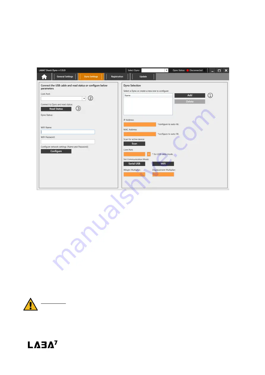
Add a new Dyno model by clicking Add button (Figure 17 – Step 1). 


a.


You can rename the model by double-clicking on the model’s name in the Dyno list.


b.


Multiple models are used to switch between them during the operation quickly. 


Figure 17


7.


Turn off the Dyno if it was previously turned on. 


8.


Connect the USB cable to the LABA7 Dyno and the computer.


9.


Wait 15-20 seconds for the Dyno to initialize. 


10.


Select the newly appeared Com Port of the connected Dyno from the drop-down menu 
(Figure 17 – Step 2).


11.


Click the Read Status button (Figure 17 – Step 3).


12.


One of the following statuses will appear: 


a.


Serial communication enabled—Dyno is configured for the USB communication 
mode. 


b.


Wi-Fi settings are not set up—Dyno is configured for the wireless communication 
mode, but the settings of a local wireless network are not configured. 


ATTENTION: Based on your preference, go to the next section for either wireless or USB 
communication setup.


Содержание Shock Dyno

Страница 1: ...LABA7 Shock Dyno User Manual Lithuania 2022...

Страница 2: ...per Removal 17 8 Software Setup 21 8 1 System requirements 21 8 2 Installation 21 8 3 Configuration 22 8 4 Wireless Communication 24 8 5 USB Communication 26 9 Software Operation 28 9 1 Main Menu 28 9...

Страница 3: ...Dyno Version 1 0 23241 Page 3 62 10 4 USB Configuration 56 10 5 USB Operation 57 10 6 Mechanical Failures 57 10 7 LED Light Indicator 58 11 Speed to load table 59 12 Warranty Information 61 13 Contac...

Страница 4: ...tructions before using the machine for the first time Observe all operating instructions and safety instructions All company names and product names are trademarks of their respective owners All right...

Страница 5: ...the power cord if it is pinched sheared or cut Do not use any power adapters if the plug doesn t fit your wall socket Do not use an extension cord The power socket to which you are connecting the Sho...

Страница 6: ...achine is straightforward to use and you can get the most accurate results immediately on your complimentary software monitoring app Shock absorber testing Check if you have the right shock for the ri...

Страница 7: ...0cm Light Shock Dyno Speed 7 2600mm s 10000N load cell Adjustable stroke 25 150mm 4HP 230V electric motor 110V available on request Scotch yoke system for accurate linear motion Mast length 130cm Mid...

Страница 8: ...7 Shock Dyno Feather and Light models is presented in the image Figure 1 below Figure 1 1 Crossbar handles 7 USB connector 2 Preload crossbar 8 Emergency stop button 3 Top mounting bracket 9 Power swi...

Страница 9: ...Heavy models is presented in the image Figure 2 below Figure 2 1 Crossbar handles 7 Manual Dyno controller 2 Preload crossbar 8 USB connector 3 Top mounting bracket 9 Emergency stop button 4 Temperat...

Страница 10: ...Manual Control Shock Dyno Mid and Heavy models can be controlled via a manual dyno controller 1 Adjust the motor frequency by rotating the knob on the manual display 2 Press the RUN button to start th...

Страница 11: ...l Clamp Assembly Fits many different shock absorbers 74mm clearance Can be used for both top and bottom mount 3 way locking bolts for extra stiffness Figure 3 Self Preload Assembly Fits shock absorber...

Страница 12: ...e tested Adjustable offset Fits 20mm and 26mm axles Standard axle mount Stock inserts 54mm and 56mm Different size inserts on request Figure 5 MTB Fork Assembly Fits steerer tube of 28 6mm Adjustable...

Страница 13: ...niversal clamp Fox 34 36 40 adapters hlins 36 38 adapters RockShox adapters Different size adapters on request Figure 7 Trunnion Assembly Fits Trunnion shock absorbers Can be used with self preload cl...

Страница 14: ...below 1 Make sure the Shock Dyno is powered off or the Emergency Stop Button is engaged before changing the adapters 2 Use a wrench tool to unscrew both vertical bolts to release the clamp heads Figur...

Страница 15: ...ncy Stop Button to disengage the Shock Dyno before mounting the damper 5 Open the safety doors by pulling from the cover side handle 6 Place the damper within the top or bottom adapter and secure it 7...

Страница 16: ...to disengage the Shock Dyno and prevent the motor from moving 2 Rotate the roller bolt using a wrench Figure 10 Step 1 and insert the locking pin to lock the roller in place Figure 10 Step 2 3 Unscrew...

Страница 17: ...round If the AC motor drive is supplied from an IT or TN power system the RFI jumper must be removed This disconnects the RFI capacities filter capacitors from the ground to prevent circuit damage and...

Страница 18: ...Shock Dyno model Figure 12 Once the cover is open you should see the AC Motor driver on the side of the Dyno towards the back next to the motor It is likely that the RFI pin jumper is located on the...

Страница 19: ...e RFI jumper is on the side of the AC Driver and is held by a bolt To remove the RFI jumper release the bolt holding the jumper Remove the jumper Tighten the bolt back Figure 13 Assemble everything ba...

Страница 20: ...Driver in a small hole It looks like a small wire To remove the RFI jumper use pliers to cut the wire or pull it out Figure 14 Assemble everything back and close the Dyno cover before powering on the...

Страница 21: ...isk space 8 2 Installation Contact LABA7 support to receive the latest Shock Dyno software version 1 Open the Shock Dyno software folder 2 Locate the Setup exe executable file and double click to run...

Страница 22: ...licking on the Select button Figure 16 Step 1 This catalog will be used to store test data files Figure 16 4 Select Communication Mode by clicking on the drop down menu Figure 16 Step 2 a Wireless com...

Страница 23: ...er 9 Wait 15 20 seconds for the Dyno to initialize 10 Select the newly appeared Com Port of the connected Dyno from the drop down menu Figure 17 Step 2 11 Click the Read Status button Figure 17 Step 3...

Страница 24: ...as previously turned on 6 Connect the USB cable to the LABA7 Dyno and to the computer 7 Wait 15 20 seconds for Dyno to initialize 8 Select the newly appeared Com Port of the connected Dyno from the dr...

Страница 25: ...refresh Figure 18 After a successful connection to the router Dyno status should indicate connected to WIFI with a green indicator in the upper right application corner ATTENTION If any of the steps...

Страница 26: ...appeared Com Port of the connected Dyno from the drop down menu 9 Click on the Read Status button 10 Note the Status that was received from Dyno Figure 19 Step 1 11 Check the Status that was received...

Страница 27: ...n 1 0 23241 Page 27 62 14 Wait up to 1 minute for the application status to refresh Figure 19 ATTENTION If any of the steps fail or the Dyno is still not connected to the application go to the trouble...

Страница 28: ...e and manage new tests Open Import existing projects and compare different tests Settings options panel containing general settings and a configuration menu for managing Dyno connectivity Figure 20 Ad...

Страница 29: ...can be changed No Subfolder If checked no sub folder will be created for the project and all the tests will be saved inside the selected data catalog Spring Force Elimination if checked allows the el...

Страница 30: ...orce and weight of the damper to eliminate it from the Dyno graphs Temperature measures and displays the temperature of the damper ATTENTION Make sure the temperature sensor that is located on the Dyn...

Страница 31: ...target temperature Speed select from the drop down menu or manually enter warmup test s speed Comments enter any comment that is specific to the test Once the Start button is clicked the Dyno will pe...

Страница 32: ...l test s speed Add Click add button to add the interval to the Intervals list Presets select an already created preset or create a new one See the next section for more details Test Type there are 2 a...

Страница 33: ...erval Presets A new dialog for editing the Presets will be shown by clicking the Presets button Presets allow the user to quickly select an already defined testing preset and save time by not needing...

Страница 34: ...Test Name enter the name of the test Comments enter any comment that is specific to the test Once the Begin Reading button is clicked the software will read the Dyno data without affecting the motor...

Страница 35: ...n the Recent Tests list it is possible to change the color of the graph In order to add a visual data point in the graph view use the left mouse button There is no limit to the number of data points U...

Страница 36: ...ing performed The horizontal axis represents the displacement 0 indicates the middle position of the stroke The vertical axis represents the force The positive force in the upper half of the graph rep...

Страница 37: ...vs Displacement Figure 28 This graph is similar to Force vs Displacement graph however it averages the test into a single line resulting in a graph without the hysteresis For details about the axes an...

Страница 38: ...damper is compressed or released at a variable speed The horizontal axis indicates the linear speed of the damper and the vertical axis indicates the resulting force The positive force at the top hal...

Страница 39: ...hange in force for variable velocity This graph is similar to Force vs Velocity however it shows the graph without the hysteresis Furthermore the speed up and the slow down of both compression and reb...

Страница 40: ...h is similar to Force vs Velocity however it shows the graph without the hysteresis The main difference between this graph and Force vs Avg Velocity is that the speed up and the slow down of both comp...

Страница 41: ...velocity plot tests represents the average change in force for a variable displacement however it is a multiple speed test see section 9 5 Interval and the graphs from different individual intervals...

Страница 42: ...d PVP test types The horizontal axis indicates the linear speed of the damper and the vertical axis indicates the resulting force The graphs consist of a limited number of data points equal to the num...

Страница 43: ...time The horizontal axis indicates the time and the vertical axis indicates the change in force Such a graph can bring value to the user as it shows the change in the force for each different rotation...

Страница 44: ...e Figure 35 Force vs Temperature graph represents the warmup of the damper It is not only available for the warmup test but also the interval or PVP test The horizontal axis indicates the change in ti...

Страница 45: ...intervals by adjusting the Numeric Intervals settings Intervals Type select between even intervals or custom option o Even Intervals automatically calculates forces and velocity based on provided vel...

Страница 46: ...clicking the Modify button a new Numeric Intervals dialog will appear Figure 37 After entering a custom velocity value in the text box a user can click Add in order to insert the custom speed into the...

Страница 47: ...e the preload force and update the zero tare value which could shift after the damper gets warmer from testing Avg Velocity Shift shifts force axis to 0 or leaves it untouched when viewing a Force vs...

Страница 48: ...en Select All contextual menu accessible by right clicking the Recent Tests list selects all tests Select None contextual menu accessible by right clicking the Recent Tests list deselects all tests Co...

Страница 49: ...and compare already created tests Figure 39 The main area presents the information of a test in the column on the left side In addition to the graph viewing and comparing similar features in New Proje...

Страница 50: ...s communication see section 8 3 Configuration for more details Language change to a different user interface language Units allows user to change different units of measurement Upon changing the units...

Страница 51: ...g Additional PVP Options shows or hides the additional PVP options such as PVP Interpolation or Live PVP Option Split Screen enables a split screen mode that displays 2 separate graphs in both New Pro...

Страница 52: ...ter icon in the status bar Figure 42 Report Type select between Summary or Detailed Report types o Summary will give you a single page report with the selected graph view and summary test information...

Страница 53: ...he following information in the Import Dialog File Contains Headers choose if the first row of the CSV file is a header row X Axis Column select which data column contains the X axis values Y Axis Col...

Страница 54: ...ersion 1 0 23241 Page 54 62 Data Export To export a selected test click on the export icon A dialog will appear showing the data that is going to be exported Click the Export button to save the data a...

Страница 55: ...s stuck on a USB connection unplug the USB cable to properly shut down the application Dyno stops during the test and when running another test dyno is not running only noise is seen on the graph Duri...

Страница 56: ...in of sight of the Dyno Test completes but the data is missing packets straight lines are visible across the graph or bad graph data is show The signal is unstable or the router application cache is f...

Страница 57: ...ng packets straight lines are visible across the graph or bad graph data is show The signal is unstable or the router application cache is full Restart the application router and or Dyno 10 6 Mechanic...

Страница 58: ...the Wi Fi network is not available Follow the Software Setup section Red The Emergency Stop button is engaged or the doors are open Blue Dyno is connecting to the wireless network Please wait Yellow...

Страница 59: ...2 2kW Stroke mm 10 25 50 75 100 Max load kg 775 311 156 103 5 77 5 Max speed mm sec 280 709 1418 2128 2837 Light Dyno Light 60hz 7 8reduction 2 2kW Stroke mm 10 25 50 75 100 120 150 Max load kg 3993...

Страница 60: ...troke mm 25 50 75 100 120 150 Max load kg 1184 592 394 296 237 197 Max speed mm sec 654 1309 1963 2618 3150 3927 Heavy Dyno HEAVY 60hz 7 8reduction 7 5kW Stroke mm 25 50 75 100 120 150 Max load kg 440...

Страница 61: ...follow the recommended maintenance schedule The repair of damages that are caused because parts or services used were not those prescribed in this manual s recommended maintenance schedule is not cove...

Страница 62: ...Lithuania info laba7 com 37062199469 Reprinting even in extract is allowed only after obtaining approval We reserve the right to make changes to the product at any time if we consider them to be in th...

Отзывы: