23
5. Operation and Performance
C Series C 88:4, C 68:4, C 48:4, C 28:4 and C 16:4 Operation Manual rev 2.2.3
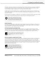
5.6.3 Mute indication
Individual channel Mute is indicated by illumination of the two yellow LEDs at the top of the channel’s LED
bargraph. If both LEDs are illuminated and all other indications are normal, then the channel has been muted by
a command from the NLB 60E front-panel or the DeviceControl application. Otherwise, a Mute could indicate a
fault condition. (See section 7.6.4 following.)
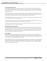
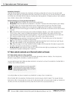
5.6.4 Performance, warning and fault indicators
▸
Power on/off
(green) indicates that mains power is switched on.
▸
NomadLink
(blue) indicates that the network is connected. The NomadLink LED will light up even before
the mains power is connected and switched on as it takes phantom power from the network cable.
▸
Bridge mode
(yellow) indicates if two channels are bridged using the DIP-switch on the rear-panel.
▸
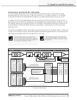
CPL,
Current Peak Limiter (orange), when flashing indicates the maximum possible current draw has been
reached.
▸
CPL,
Current Peak Limiter (orange), when constant indicates excessive current draw caused by a short
circuit on the output or very low operational impedance. When detected, the output will mute for six
seconds before re-measuring the output impedance. This will continue until the short circuit is removed.
CPL remains constant orange in a fault condition only when an input signal is present.
▸
Temperature
(yellow) warning is indicated by a flashing LED. If the amplifier goes into thermal protect
(output muted) the LED illuminates constant yellow.
▸
VHF,
Very High Frequency protection (yellow), indicates that potentially harmful continuous high frequen-
cies have been detected on the input signal. The output is muted.
▸
PAL
, Power Average Limiter (red), indicates that the amplifier is limiting because the power supply and/or
the mains inlet fuse has reached maximum capability.
▸
Hardware fault
is indicated when both the CPL and VHF indicators light up simultaneously. The amplifier
requires servicing before placing back in operation.
5.7 NomadLink network and DeviceControl software
5.7.1 NomadLink network in the amplifiers
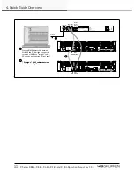
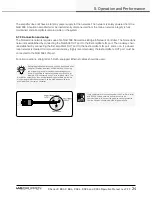
All C Series amplifiers are equipped with the proprietary NomadLink network interface. This includes two
EtherCon-housed RJ45 connections: one IN and one OUT.
Use standard straight Cat-5 Ethernet cables with RJ45 connectors to connect the amplifier to the NLB 60E or
to daisy-chain multiple amplifiers.
It is very important that two IN or two OUT ports are NEVER
connected to each other. This will cause the NomadLink
communication and DeviceControl software to exhibit erratic
behavior and display inaccurate data. However, this situation
will not damage the amplifier circuitry.
Up to 60 amplifiers can be connected to one NLB 60E in a daisy-chain or closed loop.
When the NLB 60E is powered up, the NomadLink network receives phantom power. This causes the blue
NomadLink LED on the amplifier front panel and the NomadLink LED on the rear panel to light up. NomadLink
is active even when the amplifier has mains power disconnected or is not yet powered up.


