Page 52
LAARS Heating Systems
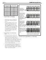
Figure 42.
Lead / Lag Operation, 3 or more boilers
Low demand -
The first boiler in
sequence fires at
less than 65%
1
2
3
4
Demand increases -
Once the first boiler
reaches 65%,
the second boiler
switches on, and
both modulate
together between 29%
and 65%
Demand increases -
Once the first two
boilers reach 65%,
the third boiler
switches on, and all
boilers modulate together
between 29% and 65%. This continues as demand increases.
5
6
7
8
Nearing max. demand -
The last boiler becomes
active. Once all boilers
reach 65%, all are
allowed to go over
65%
The Lead/Lag controller will change the firing order of
the burners, based on the run time of each burner.
Number of boilers
installed
Base load value
1
NA
2
65%
3
50%
4
35%
5
35%
6
35%
7
35%
8
35%
Figure 43.
Base Load Settings
• When the Run sequence is initiated, the
boiler with the least amount of runtime
will fire.
• If the heating demand increases so that
the firing rate of that first boiler rises to
your boiler configurations Base Load
Value
(see Figure 42)
, the next boiler in
the sequence will start up and begin firing
at 20 to 35% fan speed (depending on
your configuration). After this, the entire
configuration of boilers will modulate
up or down together, in reaction to the
changes in demand.
Control Settings for Lead/Lag System -
Part 1
1. Power up all of the boilers in the system.
2. In an installation with several boilers, you
must give each boiler a different name, sot
that the controller of the Lead/Lag Leader
can communicate with the other units. All of the units
come from the factory with a Modbus address of “1,”
so you will need to change some of these addresses.
On each unit, go to the screen for “System ID and
Access,” and enter a unique name.
3. The unit operating as the Lead/Lag Leader must be
‘Leader Enabled’ first and then set up address “1,”
and the other boilers should each be ‘Slave Enabled’
and have unique Modbus address numbers typically 2
through X (total number of boilers)
Содержание NTH
Страница 4: ...LAARS Heating Systems...
Страница 13: ...Page 9 NEOTHERM Boilers and Water Heaters 38 1 2 98 8 3 4 22 7 1 2 19 64...
Страница 30: ...Page 26 LAARS Heating Systems Figure 21 Hydronic Piping Single Boiler Zoning with Circulators...
Страница 32: ...Page 28 LAARS Heating Systems Figure 23 Hydronic Piping Multiple Boilers Zoning with Circulators...
Страница 86: ...Page 82 LAARS Heating Systems Parts Illustration 1 Jacket Components...
Страница 88: ...Page 84 LAARS Heating Systems Parts Illustration 4 Internal Components Sizes 750 850...
Страница 90: ...Page 86 LAARS Heating Systems Parts Illustration 6 Gas Train Components Sizes 600 850...
Страница 91: ...Page 87 NEOTHERM Boilers and Water Heaters Parts Illustration 7 Heat Exchanger Components 68A Sizes 285...
Страница 92: ...Page 88 LAARS Heating Systems Parts Illustration 8 Electrical Components Front Battery CR2032 Touchscreen Back...
Страница 93: ...Page 89 NEOTHERM Boilers and Water Heaters Notes...
Страница 94: ...Page 90 LAARS Heating Systems Notes...
Страница 95: ...Page 91 NEOTHERM Boilers and Water Heaters Notes...


