background image


LAARS Heating Systems

Page 106

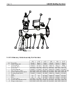
 6

3

 2

 1

 2

8

13

12

15

14

7

17

16

10

 4

 5

11

Frame and Jacket Assembly

1600

2000

2500

3000

3500

4000

Item #

Description

Part No.

Part No.

Part No.

Part No.

Part No.

Part No.

1

Base assembly

16N1000

20N1000

30N1000

30N1000

40N1000

40N1000

2

Filter

A2121700

A2121700

A2121700

A2121700

A2121700

A2121700

2a

Filter assembly (includes filter)

16N2600

20N2600

25N2600

30N2600

40N2600

40N2600

3

Stanchion

20N3010

20N3010

30N3001

30N3001

40N3001

40N3001

4

Panel, left bottom

20N3002

20N3002

30N3002

30N3002

40N3002

40N3002

5

Panel, right bottom

20N3004

20N3004

30N3004

30N3004

40N3004

40N3004

6

Extension brace, rear

30N3007

30N3007

30N3007

30N3007

30N3007

30N3007

7

Brace, upper side

20N3008

20N3008

30N3008

30N3008

40N3008

40N3008

8

Brace, lower right side

20N3047

20N3047

30N3011

30N3011

40N3047

40N3047

9

Frame mounting bracket

20N3005

20N3005

30N3012

30N3012

40N3005

40N3005

10

Brace

20N3013

20N3013

30N3013

30N3013

40N3013

40N3013

11

Panel, upper rear

16N3019

20N3019

30N3019

30N3019

40N3019

40N3019

12

Panel, center rear

16N3020

20N3020

30N3020

30N3020

40N3020

40N3020

13

Panel, lower rear

16N3021

20N3021

25N3021

30N3021

40N3021

40N3021

14

Panel, right

20N3036

20N3036

30N3036

30N3036

40N3036

40N3036

15

Strut, upper panel support

30N3043

30N3043

30N3043

30N3043

30N3043

30N3043

16

Panel, top

16N3045

20N3045

30N3045

30N3045

40N3045

40N3045

17

Brace, lower left side

20N3047

20N3047

30N3049

30N3049

40N3047

40N3047

18

Hinge mounting bracket, left

20N3163

20N3163

30N3050

30N3050

40N3163

40N3163

19

Hinge mounting bracket, right

20N3164

20N3164

30N3051

30N3051

40N3164

40N3164

20

Panel, right, rain splatter

30N3053

30N3053

30N3053

30N3053

40N3050

40N3050

21

Panel, left, rain splatter

30N3054

30N3054

30N3054

30N3054

40N3050

40N3050

22

Bracket, hinge brace

30N3055

30N3055

30N3055

30N3055

30N3055

30N3055

23

Panel, top left

20N3035

20N3035

30N3057

30N3057

40N3035

40N3035

24

Bracket, pressure switch

20N3053

20N3053

20N3053

20N3053

20N3053

20N3053

25

Cover, field connections

17J3025

17J3025

17J3025

17J3025

17J3025

17J3025

26

Gasket, .75" x .06" x 2 feet

R2074402

R2074402

R2074402

R2074402

R2074402

R2074402

Final Assembly

1600

2000

2500

3000

3500

4000

Item #

Description

Part No.

Part No.

Part No.

Part No.

Part No.

Part No.

1

Heat Exchanger Assembly

R16N2070

R20N2070

R30N2070

R30N2070

R40N2070

R40N2070

2

Plate, rear panel, gas pipe

20N3034

30N3034

30N3034

30N3034

30N3034

30N3034

3

Door, right

20N3100

20N3100

30N3100

30N3100

40N3100

40N3100

4

Door, left

20N3150

20N3150

30N3150

30N3150

40N3150

40N3150

5

Control panel assemblies:

MGH

20N7080

20N7080

30N7080

30N7080

40N7080

40N7080

MGH with CSD-1

20N7081

20N7081

30N7081

30N7081

40N7081

40N7081

MGV

20N7082

20N7082

30N7082

30N7082

40N7082

40N7082

MGV with CSD-1

20N7083

20N7083

30N7083

30N7083

40N7083

40N7083

6

Condensate trap assembly

20N2010

20N2010

30N2010

30N2010

40N2010

40N2010

7

Panel, drain access

40N3048

40N3048

40N3048

40N3048

40N3048

40N3048

8

Pressure switch

E2363100

E2362200

E2362201

E2361900

E2361900

E2361900

9

Pressure switch

E2344901

E2362000

E2363400

E2362301

E2362300

E2362300

10

Pressure switch

E2362200

N/A

N/A

N/A

E2362302

E2362302

11

Outlet box (not shown)

E2350900

E2350900

E2350900

E2350900

E2350900

E2350900

12

Spacer

F2035400

F2035400

F2035400

F2035400

F2035400

F2035400

13

Silicone rubber bumper

F2039700

F2039700

F2037900

F2037900

F2037900

F2037900

14

Bushing, nylon

S0064900

S0064900

S0064900

S0064900

S0064900

S0064900

15

Grommet, 2" pipe

S2116500

S2116500

S2116500

S2116500

S2116500

S2116500

16

Grommet, push-in

S2123600

S2123600

S2123600

S2123600

S2123600

S2123600

17

Plug, button, 7/8"

F0032300

F0032300

F0032300

F0032300

F0032300

F0032300

18

Flue Gas Sensor

E2340000

E2340000

E2340000

E2340000

E2340000

E2340000

Waterway Outlet Assembly

1600

2000

2500

3000

3500

4000

Item #

Description

Part No.

Part No.

Part No.

Part No.

Part No.

Part No.

1

Pipe, outlet manifold

20N4023

20N4023

30N4020

30N4020

40N4020

40N4020

2

PRV 75# (MGH)

A0002700

A0002700

A0000300

A0000300

A208000

A208000

PRV 125# (MGV)

A0064400

A0064400

A0000200

A0000200

A0000200

A0000200

3

Flow switch

RE0013000 RE0013000 RE0013000 RE0013000 RE0013000 RE0013000

Flow switch paddle

E2255800

E2255800

E2255800

E2255800

E2255900

E2255900

4

Well, immersion, 1/2"NPT

RE2058300 RE2058300 RE2058300 RE2058300 RE2058300 RE2058300

5

Sensor, water temperature, duplex

RE2319900 RE2319900 RE2319900 RE2319900 RE2319900 RE2319900

6

Coupling, flexible victaulic

P2086500

P2086500

P2086500

P2086500

P2086600

P2086600

7

Plug

MGH

N/A

N/A

P2088300

P2088300

P2088300

P2088300

MGV

N/A

N/A

P2080300

P2080300

P2080300

P2080300

8

Grommet, rubber

S2114000

S2114000

S2114000

S2114000

S2114000

S2114000

9

Sensor, water temperature (MGH)

RE2320600 RE2320600 RE2320600 RE2320600 RE2320600 RE2320600

10

Gauge, temp & pressure

RA0079000 RA0079000 RA0079000 RA0079000 RA0079000 RA0079000

Blower Burner Assembly

1600

2000

2500

3000

Item #

Description

Part No.

Part No.

Part No.

Part No.

1

Burner

L2019500

L2019500

L2020600

L2020600

2

Gasket, burner

S2125500

S2125500

S2125100

S2125100

3

Adapter plate

20N5037

20N5037

30N5037

30N5037

4

Sight glass

RF0044800 RF0044800 RF0044800 RF0044800

5

Flame sensor

W2014900

W2014900

W2014900

W2014900

6

Gasket, blower outlet flange

S2125600

S2125600

S2125200

S2125200

7

Venturi / Air intake assembly

A2123300

A2123300

30N5092

30N5092

8

Gasket, blower intake

20N5095

20N5095

S2125300

S2125300

9

Flow sensor, diff pressure

N/A

N/A

A2121601

A2121601

10

Blower

A2122100

A2122100

A2122100

A2122100

11

Ignitor, hot surface

W2014400

W2014400

W2014400

W2014400

12

Pilot tube

20N5088

20N5088

30N5093

30N5093

13

Compression fitting

P2085000

P2085000

P2085000

P2085000

14

Gasket, filter box flange

20N5094

20N5094

N/A

N/A

15

Pipe & flange weldment

20N5092

20N5092

N/A

N/A

16

Pipe & flange weldment

20N5090

20N5090

N/A

N/A

17

Gasket, venturi / gas valve

S2104900

S2104900

N/A

N/A

3500

4000

Item #

Description

Part No.

Part No.

1

Burner

L2019900

L2019900

2

Gasket, burner

S2124100

S2124100

3

Gasket, spacer

40N5092

40N5092

4

Pilot tube

40N5090

40N5090

5

Gasket, blower outlet flange

40N5093

40N5093

6

Flow sensor, diff pressure

A2121600

A2121600

7

Gas/air intake assembly

40N5069

40N5069

8

Gasket, blower intake

S2125300

S2125300

9

10

O-Ring

S2124800

S2124800

11

Adapter 1/4" tube x 1/8" female

P2090200

P2090200

12

Blower tube

40N5077

40N5077

13

Gasket, burner

S2124600

S2124600

14

Ignitor, hot surface

W2013900

W2013900

15

Sight glass

RF0044800 RF0044800

16

Flame sensor

W2014900

W2014900

Gas Train Assembly

1600

2000

2500

3000

Item #

Description

Part No.

Part No.

Part No.

Part No.

1

Pressure switch, low gas

R2004100

R2004100

R2004100

R2004100

2

Pressure switch, high gas

R2004000

R2004000

R2004000

R2004000

3

Elbow

P0008400

P0008600

P0008700

P0008700

4

Nipple

P0015700

P0019800

P0021200

P0021200

5

Nipple, 2"NPTx4"

P2095800

P0022600

P0022600

P0022600

6

Bushing, reducing, 1/4x1/8

P2032400

P2032400

P2032400

P2032400

7

Adapter, 2"NPTx1-1/2"NPT

P0003900

N/A

P2085700

P2085700

8

Nipple

P0053400

P2092800

P2091600

P2091600

9

Bushing, nylon

S0064900

S0064900

S0064900

S0064900

10

Gas valve, main

V2023000 

V2021200    V2021200

V2021200

11

Flange, gas valve

V2024400

V2021900

V2021900

V2021900

12

Pilot regulator

V2022100

V2022100

V2022100

V2022100

13

Ball valve, 3/8"

V2022200

V2022200

V2022200

V2022200

14

Compression fitting, 1/4" tube

NA

P2085000

P2085000

P2085000

15

Compression fitting, 1/4" tube x 1/4NPT

P0004100

P0004100

P0004100

P0004100

16

Pilot tube

16N6027

20N5086

30N6027

30N6027

17

Nipple, 1/8"x2"

P0011300

P0011300

P0011300

P0011300

18

Elbow, 1/8"

P2008900

P2008900

P2008900

P2008900

19

Nipple, 1/8"

P0011100

P0011100

P0011100

P0011100

20

Nipple/tee weldment

30N6031

30N6031

30N6031

30N6031

21

Tee, 1/8"

P0027100

P0027100

P0027100

P0027100

22

Nipple, 1/8" x close

P0011100

P0011100

P0011100

P0011100

23

Plug

70-236

70-236

70-236

70-236

24

Ball valve

V2003300

V2003300

R2011600

R2011600

25

Ball valve

V2003000

V2003200

R2011600

R2011600

26

Adapter, 1/8 FNPT x 1/8 ISO male

P2089600

P2089600

P2089600

P2089600

27

Adapter, 1/4 tube barb to 1/8 NPT male

P2097800

P2089300

P2089300

P2089300

28

Flange, adjustable shutter

V2023200

V2022400

V2022000

V2022000

29

Nipple, 1-1/2" x close

P0015500

N/A

P0019100

P0019100

30

Nipple, 3/8"x3"

P2090500

P2090500

P2090500

P2090500

31

Tee, 3/8x3/8x3/8

P2090600

P2090600

P2090600

P2090600

32

Bushing, reducing, 3/8x1/8

P2090700

P2090700

P2090700

P2090700

33

Union

P0030500

P0030700

N/A

N/A

34

Nipple

P0053400

P2072800

N/A

N/A

35

Elbow

P0008700

P0008700

P0008700

P0008700

36

Nipple

P0015700

P0015500

P0021200

P0021200

37

Nipple

P2095900

P0021200

P0021200

P0021200

38

Nozzle Orifice, 0.2 mm

P2105100

N/A

N/A

N/A

39

Washer, Sealing

S2123500

S2123500

S2123500

S2123500

3500

4000

Item #

Description

Part No.

Part No.

1

Pressure switch, low gas

R2004100

R2004100

2

Pressure switch, high gas

R2004000

R2004000

3

Elbow, 45°, 2"

P2090900

P2090900

4

Nipple, 2"x14"

P2091000

P2091000

5

Union, 2"

P0030800

P0030800

6

Nipple, 2"x6"

P0021700

P0021700

7

Ball valve

R2011600

R2011600

8

Bushing, 2"x1-1/2"

P0001400

P0001400

9

Elbow, 90°, 1-1/2"

P0009600

P0009600

10

Nipple, 1-1/2"x2.5"

P2906600

P2045300

11

Flange, adjustable shutter

V2022000

V2022000

12

Washer, sealing

S2123500

S2123500

13

Adapter, 1/8 FNPT x 1/8 ISO Male

P2089600

P2089600

14

Nipple, 1/8 x close

P0011100

P0011100

15

Tee, 1/8"

P0027100

P0027100

16

Plug, 1/8"

70-236

70-236

17

Bushing, 1/4"x1/8"

P2032400

P2032400

18

Pipe, gas inlet

40N6034

40N6034

19

Elbow, 90°, 2"

P2091100

P2091100

20

Nipple, 2"x2"

P0021100

P0021100

21

Flange, 2"

V2021900

V2021900

22

Elbow, 90°, 1/8"

P2008900

P2008900

23

Tee, 3/8"

P2090600

P2090600

24

Bushing, 3/8"x1/8"

P2090700

P2090700

25

Nipple, 3/8"x2"

P2089000

P2089000

26

Ball valve, 3/8"

V2022200

V2022200

27

Pilot regulator

V2022100

V2022100

28

Compression fitting, 1/4" tube x 1/4NPT

P0004100

P0004100

29

Pilot tube

40N6025

40N6025

30

Valve, Gas, Dungs

V2021200

V2022300  NAT   

V2021200 PROP

31

Washer, Sealing,1/8 BSPP Fitting Dungs S2123500

S2123500

32

Adapter, Fem to Male, 1/8 FNPT X 1/8 IS P2089600

P2089600

33

Valve, Manual, Brnz, 1/8 MNPTx1/8 FNP W2000300

W2000300

34

Adapter, 1/4" Barb

P2089300

P2089300

35

Pipe Plug, Malleable Iron, Black, 1/8 NP

70-236

70-236

36

Fitting, Compression, Tube, Brass

P2097200

P2097200

Control Panel Assembly

1600

2000

2500

3000

3500

4000

Item #

Description

Part No.

Part No.

Part No.

Part No.

Part No.

Part No.

1

DIN rail assembly 

30N7040

30N7040

30N7040

30N7040

30N7040

30N7040

2

Low water cutoff

RE2075100 RE2075100 RE2075100 RE2075100 RE2075100 RE2075100

3

Bushing, 7/8 nylon, open

E2074300

E2074300

E2074300

E2074300

E2074300

E2074300

4

Relay, 24VAC, DPDT

E2327800

E2327800

E2327800

E2327800

E2327800

E2327800

5

Display, touch control

E2339800

E2339800

E2339800

E2339800

E2339800

E2339800

6

Bushing, 7/8 nylon, split

S0064900

S0064900

S0064900

S0064900

S0064900

S0064900

7

High limit, manual reset

E2217800

E2217800

E2217800

E2217800

E2217800

E2217800

8

High limit, auto reset

E2217700

E2217700

E2217700

E2217700

E2217700

E2217700

9

Plug, terminal block

E2346300

E2346300

E2346300

E2346300

E2346300

E2346300

10

Vari-Prime control (MGH)

30N7067

30N7067

30N7067

30N7067

30N7067

30N7067

11

Control panel sheet metal assembly

30N7050

30N7050

30N7050

30N7050

40N7050

40N7050

22

Control module, programmed

Standard

RXN7051

RXN7051

RXN7055

RXN7051

RXN7055

RXN7051

CSD-1

RXN7052

RXN7052

RXN7056

RXN7052

RXN7056

RXN7052

Blower

A2120900

A2120900

W2014100

20N3060

18

Spark Generator

18

DETAIL

See Section 13.B.9

13.B.5    Blower Burner Assembly,  

Part Numbers (Model 2000)

Содержание MagnaTherm MGH1600

Страница 1: ...nity of this or any other appliance WHAT TO DO IF YOU SMELL GAS Do not try to light any appliance Do not touch any electrical switch do not use any phone in your building Immediately call your gas sup...

Страница 2: ...Drain Trap 25 6 E Suggested Piping Schematics 25 SECTION 7 Water Connections 7 A Water Quality 30 7 B Suggested Piping Schematics 30 7 C Piping Requirements 30 7 E Water Flow 32 7 D Condensate Drain...

Страница 3: ...86 12 A 1 Responding to a Lockout Hold or Alert 86 12 A 2 Viewing the Lockout and Alert Histories 86 12 B Troubleshooting Table 88 12 C Diagnostic Tests and Input Output Indicators 97 12 D Lead Lag Di...

Страница 4: ...LAARS Heating Systems...

Страница 5: ...Model Nomenclature 1 2 3 4 5 6 7 8 9 10 11 12 13 M G SERIES M G USAGE H HYDRONIC V VOLUME WATER SIZE MBTU h 1 6 0 0 2 0 0 0 2 5 0 0 3 0 0 0 3 5 0 0 4 0 0 0 FUEL N NATURAL P PROPANE COUNTRY CODE X USA...

Страница 6: ...domestic hot water use adjust the outlet control limit or use temperature limiting valves to obtain a maximum water temperature of 125 F 52 C WARNING The inlet gas pressure to the unit must not excee...

Страница 7: ...disturbed as a result of servicing or repair these substances become airborne and if inhaled may be hazardous to your health Do not remove or replace RCF parts or attempt any service or repair work i...

Страница 8: ...l models the Control Panel hinges forward for easy access to wiring and to the heat exchanger Touch Screen Heat Exchanger Condensing Unit Air Intake and Filter Water Outlet Water Inlet Vent Power Pack...

Страница 9: ...Air Intake and Filter Water Outlet Main Power Connections Water Inlet Vent Power Pack Field Electrical Connections Condensate Trap Heat Exchanger Condensing Unit Gas Supply Manual Gas Valve Rating Pla...

Страница 10: ...d main gas valve Blower Touch Screen Air Intake and Filter Main Power Connections Water Outlet Water Inlet Vent Power Pack Field Electrical Connections Condensate Trap Heat Exchanger Condensing Unit G...

Страница 11: ...9 8 203 38 96 57 5 147 49 8 126 4 8 12 60 8 154 2 6 7 8 4 21 6 2000 29 3 75 79 8 203 38 96 57 5 147 49 8 126 4 8 12 60 8 154 2 6 7 8 4 21 6 2500 30 8 78 87 221 41 5 105 60 5 154 60 8 154 6 5 16 71 180...

Страница 12: ...nts of the the Installation Kit box making sure that all parts are there and not damaged during shipping 1 Gromet Nylon 2 Box containing Outdoor Sensor 3 Box containing System Sensor 4 Tank Sensor 5 S...

Страница 13: ...wer floors of the structure When this type of location is not available install a suitable drain pan adequately drained under the appliance The appliance is design certified by CSA International for i...

Страница 14: ...exhaust vent pipe that is certified to ULC S636 Intake air pipe must be PVC or CPVC that complies with ANSI ASTM D1785 F441 ABS that complies with ANSI ASTM D1527 stainless steel or galvanized materi...

Страница 15: ...s listed on the following tables have been tested and authorized to safely operate with this equipment Suppliers of stainless steel and polypropylene venting that are not listed on these tables are no...

Страница 16: ...ce shall communicate with the outdoors in accordance with Method 1 or 2 See the following descriptions Where ducts are used they shall be of the same cross sectional area as the free area of the openi...

Страница 17: ...personnel Refer to the applicable codes 3 D Venting WARNING Selection of improper vent materials for installations that are installed in closets or will be operated in high ambient temperature levels...

Страница 18: ...lling this unit to use ULC S636 certified vent material consistent with the requirements as described in the Venting and Combustion Air section Class I venting systems are suitable for gas fired appli...

Страница 19: ...rtified vent system into which the vent terminal screen can be installed Be sure to install and terminate both vent and combustion air pipes per the instructions in this section 3 E Locating the Vent...

Страница 20: ...gulator vent outlet See note 4 3 feet 91 cm J Clearance to nonmechanical air supply Direct vent only 36 91cm inlet to building or the combustion air inlet Other than Direct vent 4 ft 1 2m below 36 inc...

Страница 21: ...e unit is vented through the roof the vent must extend at least 3 feet 0 9 m above the point at which it penetrates the roof It must extend at least 2 feet 0 6 m higher than any portion of a building...

Страница 22: ...ning connected to the common venting system placed in operation while the other appliances remaining connected to the common venting system are not in operation 1 Seal any unused openings in the commo...

Страница 23: ...d vacuation 2 Inspecter de facon visuelle le syst me d vacuation pour d terminer la grosseur et l inclinaison horizontale qui conviennent et s assurer que le syst me est exempt d obstruction d trangle...

Страница 24: ...ting shall be reduced at a rate of 4 percent for each 1000 ft 300 m above sea level This must be considered before selecting the equipment size 2 The gas pressure settings must match fuel type as show...

Страница 25: ...61 2 067 2 469 3 068 4 026 Length ft 10 3 520 6 790 10 800 19 100 39 000 20 2 420 4 660 7 430 13 100 26 800 30 1 940 3 750 5 970 10 600 21 500 40 1 660 3 210 5 110 9 030 18 400 50 1 480 2 840 4 530 8...

Страница 26: ...C 17 C 19 C 22 C Input Rate Headloss is for boiler only no piping Headloss is for boiler only no piping Lower flow rates may require flow switch adjustment SIZE Output Max Min 25 F Head loss Feet 30...

Страница 27: ...Headloss Flow Rate Temp Rise Headloss LPM C m GPM F Ft LPM C m 0 525 11 1 10 1 177 17 41 0 670 9 4 12 5 0 575 14 10 1 177 21 43 9 670 12 13 4 7 719 13 9 10 0 220 21 46 0 833 11 7 14 0 719 17 11 0 220...

Страница 28: ...onsult the glycol specifications or the glycol manufacturer for information about SECTION 6 Water Connection Boilers 6 A System Piping Hot Supply Connections NOTE This unit must be installed in a clos...

Страница 29: ...rain must be installed to prevent the accumulation of condensate When Figure 9 Raised concrete platform Neutralizer kit is not included 6 E Suggested Piping Schematics Figure 10 on page 26 through Fig...

Страница 30: ...ontrols Air vent 4 pipe dia max 4 pipe dia max 4 pipe dia max 4 pipe dia max Low temp radiant zone Space heating zone circuits Space heating zone circuit System pump Note This drawing is a schematic r...

Страница 31: ...iler Low temp radiant zone Low temp radiant zone Air vent Water feed controls Expansion tank 4 pipe dia max Indirect DHW tank Anti scald mixing valve Domestic hot water out Cold water Note This drawin...

Страница 32: ...radiant zone Space heating zone circuit Air vent Water feed controls Expansion tank Common piping must be sized for the combined water flow of all of the boilers 4 pipe dia max 4 pipe dia max 4 pipe...

Страница 33: ...for the combined water flow of all the boilers High temp space heating zone circuit 4 pipe dia max 4 pipe dia max 4 pipe dia max Indirect DHW tank 4 pipe Dia Max Note Indirect pump must be sized for...

Страница 34: ...Install a diaphragm type expansion SECTION 7 Water Connections 7 A Water Quality Water heaters must be installed in water conditions of 15 gpg hardness or less with a pH range of 6 5 to 9 5 pH Values...

Страница 35: ...sate is not covered by the warranty If installed indoors and there is an event such as a power outage component failure or other issue when freezing is likely the heater and system must be drained to...

Страница 36: ...most always used It is advised that the unit be installed on a raised 4 concrete platform so that there is sufficient elevation for the condensate neutralizer below the included condensate trap See Fi...

Страница 37: ...integrated 4 amp resettable fuse On three phase models a step down transformer which is protected using an appropriate din rail mounted circuit breaker generates 120 volt single 8 B Main Power Connec...

Страница 38: ...control board TB1 15A through 20A They are fed 120 Volts internally from the main power feed The current rating of the contacts is 7 4 amps and an appropriately sized contactor must be supplied and in...

Страница 39: ...re 17 Do not run any wiring to the right as this will restrict the opening ability of the Control Panel Field Electrical Connections At the front of the unit Available Electrical Raceway Available Kno...

Страница 40: ...Single unit installations Power for Field Connections must be made at Terminal Board 1 at the front of the unit 15 thru 45 of TB1 See Figure 19 and Figure 20 For single unit installations the connecti...

Страница 41: ...B 38MB2 C 39REMOTERESET 40REMOTE TOOLS 41 42 TODFEED 43 4 20MA 430 10VDC 4 20MA 44 0 10VDC CONN B CONN C 8 G Control Panel Layout Figure 20 Control Panel Layout 1 CA0099 VARI PRIME PRINTED CIRCUIT BOA...

Страница 42: ...an be controlled and monitored with a Gateway BAS using the included Modbus ports Doc 4236 The Gateway Modbus Control H2354400 for BACnet MS TP BACnet IP Modbus TCP IP Metasys N2 and LonWorks Connect...

Страница 43: ...nnections This commercial unit can be connected in Lead Lag up to a total of 8 units controllers One as the Lead control and up to 7 more as the Lag controllers For Lead Lag Connections COM2 A B and C...

Страница 44: ...DISPLAY 7 DISPLAY 8 LWCO 2 120V N P1 P2 ADDITIONAL HIGH LIMIT BLOCKED FLUE BLOCKED INTAKE THERMAL CUTOUT FLOW SWITCH HIGH GAS MANUAL RESET HIGH LIMIT TO TB1 4C 120V N TO B4 PROBE 2 1 9 2 10 3 11 4 12...

Страница 45: ...N WIRE FROM SHIELDED CABLE BL Y BL V W V OR OR W W BK W V W BK BR Y BR Y G W BK BK BK R BK Y W R W R W R GY BL BR R BR Y GY V GY BK R GY R FLAME ROD BK OR 2 1 3 4 TB1 39C TB1 40C TB1 42C TB1 43C TB1 4...

Страница 46: ...RK GENERATOR 15 7 14 6 13 5 12 4 11 3 10 2 9 1 2 TO B4 PROBE TO TB1 4C 120V N MANUAL RESET HIGH LIMIT HIGH GAS FLOW SWITCH THERMAL CUTOUT BLOCKED FLUE BLOCKED INTAKE ADDITIONAL HIGH LIMIT P1 P2 LWCO 2...

Страница 47: ...OLS VARIPRIME INSTALLED ON HYDRONIC UNITS ONLY USED ON SIZE 4 0 KBTU ONLY 2 TB1 38C TB1 37C TB1 36C BK V BR V BK O BR G BK BR R BK BR W Y J3 TB1 44C TB1 45C TB1 43C TB1 42C TB1 40C TB1 39C 4 3 1 2 BK...

Страница 48: ...1 TITLE FRACTIONS 1 8 WIRE DIAGRAM MGT HIGH VOLTAGE PANEL 110V E23606 H H N N G C B A D G 20AMP BREAKER LINE LOAD 5 4 6 1 2 3 120V 24V Y W BK BL 4 AMP HV LV 5 6 3 2 1 4 3 2 1 4 5 6 TRANSFORMER PH1500...

Страница 49: ...N DIAGRAM E23512 L1 L2 G BLOWER L1 BK L2 WIRE COLOR LEGEND BLACK BK BROWN BR RED R A B C D 4 PROPRIETARY TO LAARS HEATING SYSTEMS AND SHALL NOT BE 3 2 BY LAARS HEATING SYSTEMS DWG NO E23751 SH 1 RE SM...

Страница 50: ...WHITE W THIS DOCUMENT AND THE INFORMATION CONTAINED HEREIN ARE PROPRIETARY TO LAARS HEATING SYSTEMS AND SHALL NOT BE REPRODUCED TRANSFERRED TO OTHER DOCUMENTS USED OR DISCLOSED TO OTHERS FOR MANUFACT...

Страница 51: ...BK W R BK BK NOTE SEE WIRE DIAGRAM LABEL H2367000 AND DOCUMENT H2367100 OLOR LEGEND BK BR R O Y G BL D C B 4 3 2 THE INFORMATION CONTAINED HEREIN ARE RS HEATING SYSTEMS AND SHALL NOT BE FERRED TO OTH...

Страница 52: ...0010 A B C D 1 2 3 4 4 3 2 1 SCALE NONE INTENDED SIZE SOFTWARE DWG NO B BY LAARS HEATING SYSTEMS CO XR 1 9 17 17 013N RELEASE CHECK DRAFT ECN CHANGE REV REVISIONS RR 1 9 17 E23 PURPOSE EXCEPT AS SPECI...

Страница 53: ...LAARS HEATING SYSTEMS DWG NO E23603 SH 1 REV A CH 2 17 16 REVISIONS REV CHANGE APPR ENGR APPR ECN DRAFT CHECK UPDATED VFD CONNECTIONS A 16 017N AH 2 17 16 UNLESS OTHERWISE SPECIFIED PURPOSE EXCEPT AS...

Страница 54: ...E 120V BLOCK FLUE INTAKE SWITCHES BK W GY R GY BL G G HIGH VOLTAGE WIRE C CHART 600 480 L1 P BR L2 V O L3 T Y WIRE CO LEGEN BK B BL BR B G GY O O R V V W Y Y T P NOTES SEE WIRE DIAGRAM LABEL H23655 AN...

Страница 55: ...M PUMP BOILER PUMP J8 3 TB1 13 J8 6 J8 7 J8 11 J8 12 J4 2 J4 4 TB1 4A TB1 4A J4 6 J4 2 J4 4 J4 6 TB1 4A TB1 4A J6 3 R1 120V 120V 120V 120V 120V 120V FLOW SWITCH TB1 35C TB1 33C OUTLET WATER J8 8 J8 9...

Страница 56: ...1 J8 12 J4 2 J4 4 TB1 4A TB1 4A J4 6 J4 2 J4 4 J4 6 TB1 4A TB1 4A J6 3 R1 120V 120V 120V 120V TB1 35C TB1 34C TB1 33C OUTLET WATER INLET WATER J8 8 J8 9 J8 4 J8 10 J8 5 3 2 4 1 STACK J9 4 J9 5 J9 6 3...

Страница 57: ...3 J8 6 J8 7 J8 11 J8 12 J4 2 J4 4 TB1 4A TB1 4A J4 6 J4 2 J4 4 J4 6 TB1 4A TB1 4A J6 3 R1 120V 120V 120V 120V TB1 35C TB1 34C TB1 33C OUTLET WATER INLET WATER J8 8 J8 9 J8 4 J8 10 J8 5 3 2 4 1 STACK J...

Страница 58: ...TIONS TT ANALOG OUTDOOR SYSTEM DHW PUMP SYSTEM PUMP BOILER PUMP J8 3 TB1 13 J8 6 J8 7 J8 11 J8 12 J4 2 J4 4 TB1 4A TB1 4A J4 6 J4 2 J4 4 J4 6 TB1 4A TB1 4A J6 3 R1 120V 120V 120V 120V 120V FLOW SWITCH...

Страница 59: ...30 REMOTE RESET MB2 COM 2 DHW SENSOR PUMP 0 10V J10 3 MB2 C MB2 A DISPLAY 6 J10 6 4 20 ma 0 110VDC 43 44 45 0 10VDC J10 5 4 20 ma VARIPRIME ONLY R3 J10 8 J10 1 MB2 B VTB 3 3 VTB 3 4 120 NEUTRAL VARIP...

Страница 60: ...CTIONS TT ANALOG OUTDOOR SYSTEM DHW PUMP SYSTEM PUMP BOILER PUMP J8 3 TB1 13 J8 6 J8 7 J8 11 J8 12 J4 2 J4 4 TB1 4A TB1 4A J4 6 VFD 16 VFD 17 J4 2 J4 4 J4 6 TB1 4A TB1 4A J6 3 R1 120V 120V 120V 120V 1...

Страница 61: ...FEED J10 2 J6 8 J6 7 ALARM 27 28 26 25 24 23 22 21 TB1 4A 20 19 18 17 15 16 FIELD CONNECTIONS TT ANALOG OUTDOOR SYSTEM DHW PUMP SYSTEM PUMP BOILER PUMP J8 3 TB1 13 J8 6 J8 7 J8 11 J8 12 J4 2 J4 4 TB1...

Страница 62: ...al operation the Touch Screen will automatically present this Home screen See Menu 1 Menu 1 Home Screen Figure 38 To access the Touch Screen Figure 40 With Front Doors Open Color Status Control Icon B...

Страница 63: ...aller Password Setup and parameter changes made when the system is installed and some diagnostic and troubleshooting functions The installer level password is lnt lower case LNT User Level no password...

Страница 64: ...change a parameter that is related to safety the system will present a warning which looks like this Menu 6 Parameter Safety Warning Press OK to continue The system will ask you to login before you ma...

Страница 65: ...rify the entries in those groups in the same way Do this until the following screen shows Menu 8 Safety Parameter Reset 6 When the process is complete the system will tell you to reset the control sys...

Страница 66: ...uts used by the system Details Allows you to check the status of all of the setup parameters on the control system 9 F Configuring Parameters In this section we will give you a quick explanation of ho...

Страница 67: ...and Alert logs will be incorrect The display has a removable battery CR2032 to store time date lockout and alerts in the event of a power failure To set the clock 1 Start at the home screen Menu 14 H...

Страница 68: ...g software date codes model numbers and program name as well as giving the installer access to re name the boiler and to change the modbus addresses for lead lag operation 9 H 2 CH Central Heat Config...

Страница 69: ...ect water heaters that are used with boiler MGH systems 9 H 5 Warm Weather Shutdown Configuration Connect the outdoor reset sensor as descibed in Section 8 D From this menu you will be able to enable...

Страница 70: ...nce the system has been installed the Pump Configuration menu will allow the installer to adjust Pump control Overrun time and Demand control for the various pumps in the system 9 H 10 Statistics Conf...

Страница 71: ...quired pressures listed in Table 23 without turning on the Main valve With a call for heat enabled the unit will start the normal sequence of operation to light the pilot only Once pilot pressure has...

Страница 72: ...that as the heating demand increases the Lead Lag system puts more units on line As the heating demand is reduced the Lead Lag system shuts off some of the units The signal from the System sensor is...

Страница 73: ...or death When the Run sequence is initiated the unit with the least amount of runtime will fire If the heating demand increases so that the firing rate of that first unit rises to your unit configurat...

Страница 74: ...lave Enable You will be prompted to sign in This can be done by pressing the LOCK symbol at the top right type in LNT and press OK Then you can select Slave Enable Select Enable Slave for built in Lea...

Страница 75: ...fig Central Heat CH Config Central Heat CH Config Setpoint CH Config Setpoint CH Config Setpoint CH Config Setpoint CH Config Setpoint CH Config Setpoint CH Config Setpoint CH Config Modulation CH Con...

Страница 76: ...100 CH LL Slave CH DHW LL Slave DHW CH DHW Arrow Points to Loop with Higher Priority Arrow Points to Loop with Higher Priority Shutdown Immediately 95F Shutdown Immediately Disabled 35F 140F 10 0 0 10...

Страница 77: ...me Shutdown Immediately Shutdown Immediately Disabled 65 65F 40F 150F 0 Disabled 0 100 Enable Disable DHW CH Enabled CH DHW DHW CH Enable Disable Drop After Priority Time 240 min or 4 Hrs Boost During...

Страница 78: ...ead Lag Master Config Adv Settings Modulation Lead Lag Master Config Adv Settings Modulation Lead Lag Master Config Adv Settings Modulation 10 0 0 100 0 100 5F 20 2F 30F 0 100 210F 10F 50F 210F 0F 30F...

Страница 79: ...ee Figure 21 on page 38 For additional information on purchasing and setting up Modbus and other communication protocols contact your manufacturers representative Starting at the Home Screen tap onto...

Страница 80: ...t at 100 10 VDC or 20 mA 5 Once the Main Gas valve is energized the PCB will maintain pump output at 100 for 60 seconds to allow the system to stabilize Once the 60 sec ond timer has expired the PCB w...

Страница 81: ...enu 26 Status Summary Screen 5 From the Configuration menu select the line Burner Control Ignition Menu 27 Configuration Menu 6 Once there select Pilot Test Hold and turn this feature ON This feature...

Страница 82: ...only active when the boiler is in Run mode To setup high fire select maximum modulation then Start Test buttons Wait for the boiler to enter run and the fan speed to reach the maximum RPM Using a com...

Страница 83: ...al 9 0 0 2 25 lower than high fire CO2 0 5 to 1 2 wc Propane 10 0 0 2 25 lower than high fire CO2 0 5 to 1 2 wc 3 500 Natural 9 0 0 2 25 lower than high fire CO2 0 5 to 1 2 wc Propane 10 0 0 2 25 lowe...

Страница 84: ...devices WARNING Do not use this appliance if any part has been under water Immediately call a qualified service technician to inspect the appliance and to replace any part of the control system and an...

Страница 85: ...etup must be checked before the unit is put into operation Problems such as failure to start rough ignition strong exhaust odors etc can be due to improper setup Damage to the boiler resulting from im...

Страница 86: ...l and clean with alcohol Apply new sealing material and reassemble 11 Once a year the items listed below should be inspected by a qualified service technician 11 B Maintenance Notes Use only genuine M...

Страница 87: ...etermined to be defective install a new spark assembly in the reverse order replacing the gasket if necessary 11 B 5 Flame Sensor The flame sensor is a single rod system The minimum flame signal that...

Страница 88: ...es of the heat exchanger tubes 7 Once the tubes have been brushed clean rinse the tubes and combustion chamber with a small amount of water to rinse all of the debris out of the bottom of the flue col...

Страница 89: ...of the date and time settings The battery is a CR2032 coin type battery and has an expected service life of 6 years If the battery needs to be replaced there is a battery cover on the back of the touc...

Страница 90: ...control system is waiting for a condition to be satisfied No Reset is required to recover from an alert The system maintains a history of the 15 most recent alerts Sometimes it can be helpful to chec...

Страница 91: ...curances Press Alerts to bring up a list of the last 15 Alerts and Silence Alarm in the event of a lockout condition By silencing the alarm the audible alert has been disabled However the Lockout is s...

Страница 92: ...dule 2 Waiting for safety data verification L 1 Device in Configuration mode and safety parameters need verification and a device needs reset to complete verification 2 Configuration ended without ver...

Страница 93: ...since heating cycle starts H 24 Internal fault Spark voltage stuck low or high H 25 Internal fault Spark voltage changed too much during flame sensing time H 26 Internal fault Static flame ripple H 27...

Страница 94: ...Level Switch H 1 Reset the low gas pressure valve and the high gas pressure valve 2 Check for power at all Safety Components 3 Check wiring and correct any faults 4 Check all safety interlocks connect...

Страница 95: ...ps are correct and fault persists replace the module 92 Outlet sensor fault H 1 Check wiring and correct any possible errors 2 Replace the Outlet sensor 3 If previous steps are correct and fault persi...

Страница 96: ...ition transformer electrode flame detector flame detector siting or flame rod position 5 If steps 1 through 4 are correct and the fault persists replace the module 107 Flame lost early in run L 108 Fl...

Страница 97: ...lity to change speeds 3 Change the VFD 4 If the fault persists replace the module 130 Fan speed failed during ignition H or L 1 Check wiring and correct any potential wiring errors 2 Check the VFDs Va...

Страница 98: ...kup 4 Reset and sequence the module if code reappears replace the flame detector 5 Reset and sequence the module if code reappears replace the module 157 Combustion pressure and flame OFF L 158 Main v...

Страница 99: ...it Control Input enable setting L 200 Invalid lightoff rate setting L 201 Invalid lightoff rate proving setting L 202 Invalid MFEP Main Flame Establishing Period time setting L 203 Invalid MFEP Main F...

Страница 100: ...er high limit setpoint setting L 228 Invalid Stack limit setpoint setting L 229 Invalid Modulation output setting L 230 Invalid CH Central Heat demand source setting L 231 Invalid Delta T limit delay...

Страница 101: ...uts displayed The Burner Control I O button leads to Menu 39 Menu 39 Burner Control I O Screen A green dot indicates a function that is on 2 Press the Digital I O button to see parameters with the fun...

Страница 102: ...of burner cycles etc Menu 45 Statistics Configuration Screen 12 F Analysis The control system includes an Analysis branch that can display the behavior over a period of time for several different para...

Страница 103: ...w switch gas pressure switches LWCO and High Limit aquastats are completed the unit will start the blower and begin the ignition sequence The unit is equipped with a low and high fire air pressure swi...

Страница 104: ...21 8 9 D 14 23 SHOWN FOR REF ONLY 2 A AC DISTRIBUTION BOX G SECTION 13 Replacement Parts Use only genuine Manufacturer replacement parts 13 A General Information To order or purchase parts contact you...

Страница 105: ...p left 20N3035 20N3035 30N3057 30N3057 40N3035 40N3035 24 Bracket pressure switch 20N3053 20N3053 20N3053 20N3053 20N3053 20N3053 25 Cover field connections 17J3025 17J3025 17J3025 17J3025 17J3025 17J...

Страница 106: ...LAARS Heating Systems Page 102 1 13 12 4 3 5 13 2 15 Final Assembly DETAIL A 9 10 8 DETAIL Final Assembly...

Страница 107: ...J3025 17J3025 17J3025 17J3025 17J3025 26 Gasket 75 x 06 x 2 feet R2074402 R2074402 R2074402 R2074402 R2074402 R2074402 Final Assembly 1600 2000 2500 3000 3500 4000 Item Description Part No Part No Par...

Страница 108: ...2022200 V2022200 27 Pilot regulator V2022100 V2022100 28 Compression fitting 1 4 tube x 1 4NPT P0004100 P0004100 29 Pilot tube 40N6025 40N6025 30 Valve Gas Dungs V2021200 V2022300 NAT V2021200 PROP 31...

Страница 109: ...ater Heaters Page 105 A 12 10 1 2 2 3 6 16 8 7 11 13 15 14 4 9 5 A 12 10 1 2 2 3 6 16 8 7 11 13 15 14 4 9 5 W2014100 20N3060 17 Spark Generator 17 DETAIL 16N5074 13 B 4 Blower Burner Assembly Part Num...

Страница 110: ...Part No Part No 1 Burner L2019900 L2019900 2 Gasket burner S2124100 S2124100 Item Description Part No Part No Part No Part No Part No Part No 1 Heat Exchanger Assembly R16N2070 R20N2070 R30N2070 R30N2...

Страница 111: ...o 1 Heat Exchanger Assembly R16N2070 R20N2070 R30N2070 R30N2070 R40N2070 R40N2070 2 Plate rear panel gas pipe 20N3034 30N3034 30N3034 30N3034 30N3034 30N3034 3 Door right 20N3100 20N3100 30N3100 30N31...

Страница 112: ...E0013000 RE0 Flow switch paddle E2255800 E2255800 E2255800 E22 4 Well immersion 1 2 NPT RE2058300 RE2058300 RE2058300 RE2 5 Sensor water temperature duplex RE2319900 RE2319900 RE2319900 RE2 6 Coupling...

Страница 113: ...MagnaTherm Boilers and Water Heaters Page 109 1 2 3 12 10 7 9 8 14 13 4 5 6 AC DISTRIBUTION BOX ASSEMBLY PART NUMBERS MODEL1600 13 B 8 AC Distribution Box Assemblies and Part Numbers Model 1600...

Страница 114: ...LAARS Heating Systems Page 110 6 3 2 1 2 8 13 12 17 16 10 AC DISTRIBUTION BOX ASSEMBLY PART NUMBERS AND BLOWER MODEL 2000 13 B 9 AC Distribution Box Assembly and Blower Part Numbers Model 2000...

Страница 115: ...8 D T L P C N I Z C N U 6 1 8 3 T U N 0 0 1 3 0 0 0 F 6 1 6 1 16 16 F2037700 WASHER THICK FLAT 3 8 STEEL ZINC PLATED 13 16 OD 7 6 L E E T S S S E L N I A T S L 2 1 X 8 W E R C S 0 0 9 6 0 0 2 F 2 2 5...

Страница 116: ...Heating Systems Page 112 28 26 38 39 26 23 27 16 31 23 20 5 35 11 10 29 7 25 34 37 1 24 9 12 13 14 3 3 4 36 2 17 19 26 39 39 9 6 6 21 17 18 22 30 32 15 8 33 Gas Train Assembly Models 1600 2000 2500 an...

Страница 117: ...5086 30N6027 30N6027 17 Nipple 1 8 x2 P0011300 P0011300 P0011300 P0011300 18 Elbow 1 8 P2008900 P2008900 P2008900 P2008900 19 Nipple 1 8 P0011100 P0011100 P0011100 P0011100 20 Nipple tee weldment 30N6...

Страница 118: ...l 1 70 236 PIPE PLUG MA 1 W2000300 VALVE MANUA 2 S2123500 WASHER SEA 2 P2089600 ADAPTER FEMALE 1 P2089300 ADAPTER 1 4 TUB 1 40N6040 GAS TRA 1 40N6031 GAS TRAIN 1 V2022300 VALVE 18 23 24 16 22 14 13 12...

Страница 119: ...90700 P2090700 25 Nipple 3 8 x2 P2089000 P2089000 26 Ball valve 3 8 V2022200 V2022200 27 Pilot regulator V2022100 V2022100 28 Compression fitting 1 4 tube x 1 4NPT P0004100 P0004100 29 Pilot tube 40N6...

Страница 120: ...h E2344901 E2362000 E2363400 E2362301 E2362300 E2362300 10 Pressure switch E2362200 N A N A N A E2362302 E2362302 11 Outlet box not shown E2350900 E2350900 E2350900 E2350900 E2350900 E2350900 12 Space...

Страница 121: ...MagnaTherm Boilers and Water Heaters Page 117 Notes...

Страница 122: ...LAARS Heating Systems Page 118 Notes...

Страница 123: ...MagnaTherm Boilers and Water Heaters Page 119 Notes...

Страница 124: ...rk All marks have a white outline If the mark MUST rev the PMS 300 mark white outline H2359200J Customer Service and Product Support 800 900 9276 Fax 800 559 1583 Headquarters 20 Industrial Way Roches...

Отзывы: