


INSERTO Crystal
50 – 50v – 50v p30 – 70 – 80 – 100
6096801 – EN
21
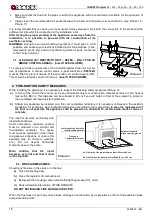
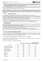
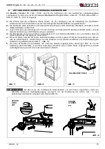
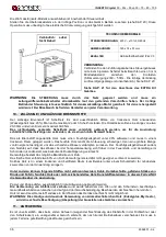
CHIMNEY CAPS - DISTANCES AND POSITIONING
UNI 10683/98
Inclination of the
roof
Distance between the roof
ridge and the stack
Minimum height of the stack
(measured from the outlet)
α
αα
α
A
(m)
H
(m)
15°
< 1.85 m
0.50 m above the roof ridge
> 1.85 m
1.00 m from the roof
30°
< 1.50 m
0.50 m above the roof ridge
> 1.50 m
1.30 m from the roof
45°
< 1.30 m
0.50 m above the roof ridge
> 1.30 m
2.00 m from the roof
60°
< 1.20 m
0.50 m above the roof ridge
> 1.20 m
2.60 m from the roof
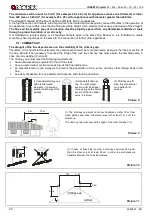
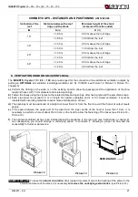
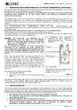
6. VENTILATION HOOD OR ADJACENT LOCAL
The
INSERTS
Cryst al 70 / 8 0 / 1 00
are pre-arranged for the connection of two additional ventilation outputs, by
putting an
OPTIONAL
kit ventilation (centrifugal ventilator, art. Nr. 1318000, see Picture 12,
Picture 13, Picture 15 –
chapter 9)
a)
Perform the drilling on the walls or on the existing hood to allow the passage and the application of the (fire-
resistant) hoses with 15 cm diameter and related openings.
b)
Fasten the hoses using the clamps to the related collars and openings, after having removed the semi-blank caps.
c)
Each pipe must not exceed 1.5 m of length for natural ventilation and 4 m for forced ventilation; it must be
insulated with insulating materials to avoid noise and dispersion of heat.
d)
The openings must be positioned at a height not lower than 2 m from the floor to avoid that hot air at output meets
people.
e)
If the space between the upper part of the insert and the lower profile of the hood is lower than 10 cm, it is
necessary to perform a hole of about 30 x 40 cm on the hood to allow the fastening of the hoses (see Picture 12 –
Picture 13).
f)
The optional ventilation kit has to be installed below the appliance in the rear part (see instructions in chapter 9).
As consequence you should arrange a underlying space to collocate it, allowing a proper air flow and the
accessibility for future maintenance.
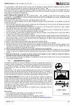
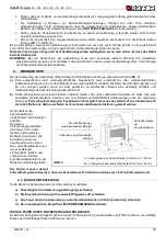
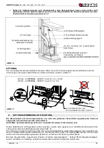
INSERTO 50V-p30:
To ease the
natural circulation
of air (upward movement due to the heating of the same) in the
external enclosure of the stack, it is necessary
to remove the underlying semi-blanks
. (see Picture 14).
Picture 12
Picture 13
Picture 14
SEMI-BLANKS


