background image

Methods  and  apparatus  disclosed  and  described  herein  have 

been developed solely on company funds. No government or other 

contractual  support  or  relationship  whatsoever  has  existed  which 

in any way affects or mitigates proprietary rights of ACSS

®

 in these 

developments.  Methods  and  apparatus  disclosed  herein  may  be 

subject to U.S. Patents existing or applied for. ACSS

® 

reserves the right 

to add, improve, modify, or withdraw functions, design modifications, 

or products at any time without notice.
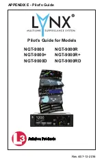
Pilot’s Guide

Product Part No. 9029000-20000 (panel mount)

9029000-40000 (remote mount)

Document Part No. 0040-17000-01 (Revision E)

© Copyright 2015

ACSS 

®

Refer to the following for additional copyright information: 

https://www.l-3avionics.com/open-source.aspx
https://www.l-3avionics.com/customer-support/

flight-data-info/open-source-software-report.aspx 

Trademarks

Lynx 

®

 is a registered trademark of L-3 Avionics Systems

Patent Pending

Pilot’s Guide

i

Export Notice

This  technical  data  is  controlled  under  the  Export  Administration 

Regulations  (EAR)  and  may  not  be  exported  without  proper 

authorization by the U.S. Department of Commerce.

L-3 Avionics Systems. 
5353 52nd Street, S.E. 
Grand Rapids, MI 49512 USA 
Customer Support (800) 453-0288  
International (616) 949-6600  
FAX (616) 977-6898 
www.L-3avionics.com

Avionics Systems

Distributed with permission by:

Содержание Lynx NGT-9000

Страница 1: ...Aviation Products NGT 9000 NGT 9000 NGT 9000D Pilot s Guide for Models NGT 9000R NGT 9000R NGT 9000RD APPENDIX E Pilot s Guide Rev 4 07 13 2016 ...

Страница 2: ...s not replace a pilot s see and avoid responsibility This equipment is not approved as a collision avoidance tool Any deviation from an air traffic control clearance based on cockpit information must be approved by the controlling ATC facility prior to commencing the maneuver Uncoordinated deviations may place an aircraft in close proximity to other aircraft under ATC control not seen on the airbo...

Страница 3: ...remote mount Document Part No 0040 17000 01 Revision E Copyright 2015 ACSS Refer to the following for additional copyright information https www l 3avionics com open source aspx https www l 3avionics com customer support flight data info open source software report aspx Trademarks Lynx is a registered trademark of L 3 Avionics Systems Patent Pending Pilot s Guide Export Notice This technical data ...

Страница 4: ...hable Configuration Module DCM 1 14 Directional Antenna 1 15 Alternate Displays 1 15 Personal Electronic Device PED 1 15 WiFi Serial Adapter 1 15 CP 2500 Control Panel 1 15 Chapter 2 Operation Introduction 2 1 Power Remote Mount 2 1 Normal Operation Remote Mount 2 2 Power panel Mount 2 2 Splash Screen 2 2 System Status Versions Screen 2 3 Flight ID Screen optional 2 4 Normal Operation 2 4 Basic Op...

Страница 5: ...en 2 19 Options Status 2 19 Options Settings 2 20 Selected Traffic Button i 2 21 TIS B No Coverage Indicator 2 22 Traffic Information Window 2 22 Selected Traffic ID 2 23 Selected Traffic GS 2 23 True Track TRK 2 23 Weather Operation 2 24 FIS B No Coverage Indicator 2 24 FIS B Graphic Application 2 25 Map Elements 2 25 Information Button i 2 26 TFR Map Elements 2 26 AIRMET and SIGMET Map Elements ...

Страница 6: ...B Textual Application 2 37 Display Area 2 37 Banner 2 37 Traffic Button 2 37 Airport Button 2 38 Edit Airport ID Window 2 38 Favorites Button 2 39 Favorites Pick List Window 2 39 Product Button 2 40 Product Pick List Window 2 40 Maintenance Mode 2 40 Chapter 3 Controls and Indicators Introduction 3 1 Cockpit Switches 3 1 IDENT 3 1 Indicator lamps 3 1 TAS Alert 3 1 ADS B Fail 3 1 Control Panel Opti...

Страница 7: ...oduction 4 1 Sensitivity Levels 4 1 Sensitivity Level A 4 1 Sensitivity Level B 4 2 Audio Inhibit 4 2 Audio Inhibit GPWS or EGPWS 4 4 TA Symbol Duration 4 4 Other aircraft ground Filtering 4 4 Interference Limiting 4 4 Chapter 5 Troubleshooting Introduction 5 1 General display conditions 5 1 System Status Messages 5 3 Invalidities 5 4 Appendix A Record Of Important Information A 1 Table of Content...

Страница 8: ...16 On Off Options Screen 2 30 Figure 2 17 Weather Map Legend Screen 2 31 Figure 2 18 Declutter Option Screen 2 32 Figure 2 19 Weather Map Text Screen 2 33 Figure 2 20 Product Pick List Window 2 34 Figure 2 21 Aloft Map Screen 2 34 Figure 2 22 Winds Aloft Map Elements 2 35 Figure 2 23 FIS B Textual Application 2 37 Figure 2 24 Example Of Edit Airport ID Window 2 38 Figure 2 25 Example Of Favorites ...

Страница 9: ...nt EAR Export Administration Regulations EGPWS Enhanced Ground Proximity Warning System FAA Federal Aviation Administration FDE Fault Detection and Exclusion FIS B Flight Information Service Broadcast fl Foot Lambert ft Feet ft min Feet Per Minute GA General Aviation GBT Ground Based Transceiver GALT GPS Altitude GND Ground GPS Global Positioning System GS Ground Speed GPWS Ground Proximity Warnin...

Страница 10: ...ing REF Reference RTCA Radio Technical Commission for Aeronautics Inc SBAS Satellite Based Augmentation System SIGMET Significant Meteorological Information SIL Source Integrity Level SPECI Aviation Special Selected Weather SPI Special Identification STBY Standby SUA Special Use Airspace SSR Secondary Surveillance Radar TA Traffic Advisory TAF Terminal Aerodrome Forecast TAS Traffic Awareness Syst...

Страница 11: ...splays See Figure 1 1 The remote version of the Lynx NGT 9000 provides the same functionality as the panel mount but is controlled using a compatible alternate display or controller See Figure 1 2 In addition to ADS B surveillance some models of the Lynx NGT 9000 include an Active Traffic Awareness System TAS as well as support for antenna diversity Table 1 1 provides model and part number informa...

Страница 12: ...ning System GPS ADS B TIS B Receive 1090ES UAT ADS B Transmit 1090ES FIS B UAT Mode S Transponder Diversity optional Traffic Awareness System TAS optional Service Life Unlimited Scheduled Maintenance No scheduled maintenance is required As a transponder device FAA document 91 413 re quires testing and inspection of a transponder every 24 months Repairs Repairs performed at the FAA certificated Re ...

Страница 13: ...PS ADS B TIS B Receive 1090ES UAT ADS B Transmit 1090ES TIS B 1090ES FIS B UAT Mode S Transponder Diversity optional Traffic Awareness System TAS optional Service Life Unlimited Scheduled Maintenance No scheduled maintenance is required As a transponder device FAA document 91 413 re quires testing and inspection of a transponder every 24 months Repairs Repairs performed at the FAA certificated Rep...

Страница 14: ...own aircraft that it is treated as a new intruder and displayed This is not an error or malfunction in the system As ground stations improve the occurrence of these shadows should be minimized or eliminated Ground stations only produce TIS B intruders for Mode C S equipped aircraft that have no ADS B output Mode A or non transponder equipped aircraft are not reported as TIS B intruders It is the p...

Страница 15: ...on is shown on a optional compatible display or PED See Figure 1 2 Figure 1 2 Example of Remote Mount Lynx NGT 9000 The Lynx NGT 9000 replies to Mode A Mode C and Mode S interrogations on 1030 MHz and transmitting responses at 1090 MHz Ground stations can interrogate Mode S Transponders individually using a 24 bit ICAO Mode S address which is unique to the particular aircraft In addition ground st...

Страница 16: ...e capability to interrogate nearby aircraft transponders and issue Traffic Advisory TA alert to the flight crew This option requires the installation of a directional antenna The Diversity option offers enhanced traffic awareness via 1090MHz using the ADS B service This option requires the installation of an additional top mounted UAT L Band antenna The unit provides the transponder code reply sym...

Страница 17: ...ed by the ground station if within a 15 nm horizontal range and 5 000 ft of altitude of the receiving aircraft ADS B equipped ground aircraft and vehicles are not displayed to airborne aircraft An aircraft on the ground receiving ADS R is provided both ground aircraft and vehicles as well as airborne other aircraft within 5nm and 2 000 ft above ground level of the airport reference point Receiving...

Страница 18: ...pped with a transponder or equipped with a Mode A only transponder are not part of the TIS B data and will not be seen on the traffic display The ground station will not provide display information for Mode C and Mode S transponder equipped aircraft that do not provide altitude information An aircraft on the ground receiving TIS B is provided both ground aircraft and vehicles as well as airborne o...

Страница 19: ... UAT 1090ES TAS Traffic 70 nm TAS 10000 TAS 3500 ft TIS B Own Aircraft UAT 1090ES TAS model option 5000 ADS R 30 nm TIS B ADS R ATC Ground Station Other Aircraft UAT Non Equipped Mode A C Equipped TIS B Other Aircraft UAT FIS B TIS B Other Aircraft TAS Other Aircraft 1090ES ADS R ...

Страница 20: ...he visual acquisition of aircraft that may represent a danger Traffic information out to a selected range is graphically displayed on the NGT 9000 or alternate display The system display shows the relative position of traffic using text shapes i e Traffic Advisory solid circle Other Traffic open diamond Proximate Traffic solid diamond and colors The effective active mode surveillance range is 35 n...

Страница 21: ... primary weather products i e aviation weather to meet operational and safety requirements Official weather products primary products can be obtained from a variety of sources including ATC FSSs and if applicable AOCC VHF HF voice which can transmit aviation weather NOTAMS and other operational aeronautical information to aircraft in flight FIS B augments the traditional ATC FSS AOCC services by p...

Страница 22: ... in a mosaic map which shows patterns of precipitation and its movement The Regional NEXRAD FIS B product is a com posite of available NEXRAD radar imagery in a local area showing a more detailed image than the CO NUS NEXRAD product NEXRAD CONUS Graphical report The CONUS NEXRAD FIS B product is a summary composite of available NEXRAD radar imagery across the 48 states NOTAM Text graphical report ...

Страница 23: ...s can cover an 18 or 24 hour period TAFs complement and use similar encoding to METAR reports They are produced by a human forecaster based on the ground For this reason there are fewer TAF locations than there are METARs TAFs can be more accurate than Numerical Weather Forecasts since they take into account local smallscale geo graphic effects Winds and Tempera tures Aloft Graphical report Winds ...

Страница 24: ...ation and Satellite Based Augmentation Systems SBAS The Lynx NGT 9000 have an internal GPS function that provides position velocity time and integrity NIC NAC etc informa tion to the ADS B functions The antenna is located on the top of the aircraft L Band Antenna The L Band antenna is used by the Lynx NGT 9000 to receive 1030MHz receive and transmit 1090MHz and receive 978MHz It is located on the ...

Страница 25: ...0 supports the use of personal electronic devices e g tablets via a WiFi connection The PED must use compatible applications that support the ADS B broadcast services i e ADS B In TIS B ADS R and FIS B Check with an avionics dealer or contact L 3 Avionics Systems for a current list of compatible applications WiFi Serial Adapter The Lynx NGT 9000 can be connect to a PED via WiFi using a compatible ...

Страница 26: ...Lynx NGT 9000 Pilot s Guide 1 16 Description Page intentionally blank ...

Страница 27: ... begins within 20 seconds of applying power During start up the unit checks for valid configuration data and initializes self tests The GPS begins initializing If installed and On Ground the CP 2500 displays no message for first 2 minutes than displays GPS INIT indefinitely until a GPS position is acquired If an ADS B System Fail is displayed after approximately 2 minutes then the GPS position was...

Страница 28: ...ns to normal operation within 5 seconds bypassing the splash version and flight ID screens Splash Screen The splash screen is displayed in less than 5 seconds after power is applied The company name Logo is shown on the left side and the product name on the right See Figure 2 1 Figure 2 1 Example of Splash Screen Normal Operation remote mount Operational control of the remote mount version of the ...

Страница 29: ...iled is heard through the aircraft audio system The option to restart the unit or to continue start up in a degraded mode is shown on the right side of the display Tap the Restart button to restart the system If the System Fail message continues to be seen tap the Continue button to proceed Refer to Chap 5 Troubleshooting for corrective actions If System Status is System Degraded then the message ...

Страница 30: ...t ID The Flight ID Number is entered using the keypad The keypad will change to numbers after three alpha characters are entered When complete tap the Done button to proceed to normal operation The last Flight ID entered is shown after power is cycled Figure 2 3 Example of Flight ID Screen Normal Operation Figure 2 4 shows an example of the unit in normal operation When the aircraft is on ground t...

Страница 31: ...ted Basic Operation The touch screen display is divided into left and right screens that show information specific to the selected application The user can select input and adjust information on the screen using buttons edit boxes and screen objects using gestures actions such as tap momentary press drag or swipe Screen Buttons The buttons are used to select input and adjust screen information The...

Страница 32: ... Used to increase or decrease the display brightness level Tap the button to open a slide bar The button is blue only while pressed Not Selected Selected Scroll Bar The scroll bar is used to navigate vertically through a list or block of text Use a drag or swipe action to move the scroll bar Scroll Bar Position Indicator Slider Bar A slider bar is used to increase or reduce a value Use a drag or s...

Страница 33: ...the message text Self Test Failures Occured Self Test Failures Occured Restart Continue Message Text Function Activate Buttons Table 2 1 Button Functions continued Application Screens The display is divided into left and right screens with each screen having access to a particular application An Application indicator is located at the bottom of each screen The indicator shows the number of availab...

Страница 34: ...ts of AC 20 172A and DO 317A for the purpose of supporting the Enhanced Visual Acquisition EVAcq and Basic Airborne AIRB CDTI applications FIS B Graphic Simplified moving map display with depiction of ownship and the ability to selectively overlay graphical FIS B products such as NEXRAD METAR AIRMET SIGMETs and TFR FIS B Graphic Winds Temp Simplified moving map display with depiction of ownship an...

Страница 35: ... the Squawk Code Edit Screen is shown See Figure 2 6 The current Squawk Code continues to be transmitted until the last digit of the new Squawk Code is entered The edit mode is cancelled by tapping the Squawk Code before the fourth digit is entered or after 5 seconds of inactivity or if a TAS alert occurs MSG ON GND ON GND Indication System Test I D E N T 1200 PALT 12000ft ID N333TL IDENT Squawk V...

Страница 36: ...r inATC modeAin which it replies to interrogations but does not report the plane s altitude Selecting ALT put the transponder in ATC mode C When the aircraft is In Air the transponder replies to interrogations and includes the plane s pressure altitude in the replies When On Ground the display includes an ON GND indication While On Ground the transponder does not reply to All Call interrogations a...

Страница 37: ...he previously viewed screen Refer to the Chap 5 Troubleshooting for corrective actions ON GND Indicator The ON GND indicator provides the pilot a notification that the transponder is operating in the on ground mode does not reply to all calls System Test Button The System Test button is available only when the aircraft is on the ground Tapping the button initiates the Test During the System Test t...

Страница 38: ... any of the system functions then the message Service Unit Soon is shown on the right side of the display Tap Continue screen button to proceed Correct failures before going any further with the functional check Note It is normal to show degraded for certain functions if some aircraft systems are still aligning or if the GPS has not yet acquired a signal On the Transponder Screen tap the MSG butto...

Страница 39: ... another aircraft cannot meet these requirements then the other aircraft will not be displayed on the Lynx NGT 9000 The EVAcq and AIRB functions are unavailable when ownship position is beyond 85 degrees North or South latitude The result is a display of Traffic Unavailable on Panel mount units and an indication of Standby for remote displays However for NGT 9000 installations where TAS is enabled...

Страница 40: ...uding the clock position relative attitude and range 10 o clock low 5 miles This is a configurable option selected at the time of installation A solid diamond or arrowhead is a Proximity Advisory PA that represents traffic that is close but does not pose an immediate collision threat A hollow diamond or arrowhead indicates Other Traffic OT that represents traffic that does not pose an immediate th...

Страница 41: ... traffic symbol generates a circle around it indicating that the traffic symbol is selected In addition the following is displayed Selected Traffic Info Button Selected Traffic ID and if enabled the Selected Traffic Ground Speed GS Tap the traffic symbol again to remove the circle and data When TAS functionality is enabled and in installations with no heading source the TAS traffic referenced to h...

Страница 42: ...Ground Directional OT Ground Vehicle Directional On Ground Non directional OT Ground Vehicle Non directional 01 Airborne Directional TA Traffic symbol with a data tag indicating a relative altitude of 100ft below with a horizontal velocity vector Panel mount only 08 Airborne Directional Other Traffic symbol with a data tag indicating a relative altitude of 800ft below own aircraft descending with ...

Страница 43: ...e ranges are in relation to the ownship A description of each mode is detailed below Normal NRM Traffic is displayed from altitudes of between 2 700 and 2 700 ft This mode is typically used during the enroute phase of flight to reduce screen clutter Above ABV Traffic is displayed from altitudes of between 9 000 and 2 700 ft This mode is typically used during takeoff Below BLW Traffic is displayed ...

Страница 44: ...ed operations 7 knots ADS B tracks are removed because ownship track can not be adequately determined If TAS is not active a Traffic Unavailable message is displayed Transponder Banner When the traffic application is displayed on the left screen the transponder banner is displayed at the top of the left screen with the following information Quick return button is labeled XPDR and is used to return...

Страница 45: ...in all the traffic symbols being removed from the traffic screen Traffic Options Button The gear shaped Options Button is located in the upper right corner of the right application screen Tap the button to open the options screen Traffic Options Screen Three latch buttons are located on the bottom The Status button opens a screen showing GPS satellite information The Settings button opens a screen...

Страница 46: ...ng provided by FDE SIL This value is always 3 Displayed GPS Satellite information is shown as horizontal bars in increasing numerical order The bars are green filled for greater signal strength and gray filled when no signal is detected The bars should be at least 40 50 green filled Latitude and Longitude data Shows the GPS computed own aircraft latitude longitude in degrees minutes seconds GPS Al...

Страница 47: ...control The VFR Code button is a means to update the default VFR code to use when the Squawk VFR button is pressed on the transponder application screen Tap the button to go to a VFR Code edit screen to set a new VFR code NOTE This should be set to 1200 for use in the USA A Flight ID toggle button is shown if configured Tap the button to open the Flight ID Edit screen Figure 2 11 Traffic Options S...

Страница 48: ...al i e installed not failed not in standby Traffic Information Window The window is shown over the traffic screen and provides the following data and functionality Flight ID of the selected aircraft Emitter Category or type of aircraft An aircraft Icon is shown on the right side of the window showing a representation of the aircraft being tracked A question mark is inserted if no icon for that typ...

Страница 49: ...e figure 2 8 Selected Traffic GS The Selected Traffic GS if configured appears along the right side of both screens under the selected traffic ID after a traffic symbol is pressed The Traffic GS is removed when the selected traffic symbol is tapped a Traffic Advisory TA occurs or if the selected traffic is no longer being tracked The Traffic GS is restored to the screen if the Traffic Advisory is ...

Страница 50: ...S B No Coverage Indicator When configured to be enabled the indicator is located at the bottom center of the screen and is shown when No FIS B data is available in the area i e out of range of a ADS B ground station The indicator is also shown if a problem exists with the NGT 9000 System See the troubleshooting section When configured to be disabled the Winds Temps and FIS B textual data screens a...

Страница 51: ...on Button No Coverage Indicator Map Elements FIS B weather products are overlaid on the map The viewing of weather products is controlled by the declutter range selected on the Options Screen Tap to select Product overlaid map elements The selected map elements are highlighted in a yellow outline A tap of an empty area of the map de selects the map element Only one map element can be selected at a...

Страница 52: ...t types of airports are described in Table 2 5 Soft surfaced airports are shown at display ranges less than or equal to 10 nm Hard surfaced small airports are shown at display ranges less than or equal to 20 nm Hard surfaced large airports are shown at display ranges less than or equal to 200 nm Information Button i The Information button is shown on the screen located on the right side of the scr...

Страница 53: ...urfaced Large Airports 8 069 ft runway and some multi surfaced 8 069 ft runways Non towered Hard Surfaced Large Airports 8 069 ft runway and some multi surfaced 8 069 ft runways AIRMET Type Display Properties Icing Straight hashed blue line Turbulence Straight hashed orange line Mountain Obscuring Straight hashed magenta line IFR Straight hashed purple line Unknown Straight hashed blue line SIGMET...

Страница 54: ...CONUS Map Elements CONUS information covers the Continental United States It is only updated every 15 minutes Flight Rules Display Properties VFR Filled cyan circle MVFR Filled green circle IFR Filled yellow circle LIFR Filled magenta circle Unknown Filled grey circle Figure 2 15 Example of NEXRAD Weather Map METAR METAR is a report of weather conditions at airports represented graphically and con...

Страница 55: ...ate the panning function North Indicator This indication is a white green arrow located in the lower right corner of the display The indicator points to the top of the display when the application is oriented north up and points true north when the application is oriented track up Airport ID Indicator The airport ID is shown on the screen located below the Information button after an airport map e...

Страница 56: ...On See Figure 2 16 Weather Map Legend Screen The Legend screen is located on the left screen and is shown after the Legend button in the On Off screen is tapped The screen has a banner on the top of the screen above the left display area See Figure 2 17 Banner The Banner is shown on the top of the screen having a gray background The banner provides the following information Done button used to ret...

Страница 57: ...Lynx NGT 9000 Pilot s Guide 2 31 Operation Figure 2 17 Weather Map Legend Screen ...

Страница 58: ...ed with the declutter range scale from 10 to 800 The Declutter setting sets the zoom range when a product is displayed removed from the display The display area shows the declutter list of the different products NEXRAD METAR TFR AIRMET and SIGMET LED indicators show declutter ranges for each product The selected list item is highlighted in white Use the Zoom buttons to increase and decrease the la...

Страница 59: ...utton opens a Product Select window The button is displayed only when the selected display element is an airport See Figure 2 20 If selected product text data report is not available the display area indicates this by displaying the selected product with a not available message Weather Map Text Screen The Weather Map Text is shown on the left screen after the Information button is tapped The scree...

Страница 60: ...layed on the Weather Map Text screen If data for that product type is not available the message not available is displayed Figure 2 20 Product Pick List Window FIS B Graphic Winds Temp Application The Graphical Winds and Temperature Application is available on the right screen and is located in the third screen position as indicated by the Application Indicator This application screen displays gra...

Страница 61: ...his button is located on the far left side of the screen and is labeled TFC with a left facing triangle Tap the button to return to the Traffic Application screen The winds aloft display properties are defined in Figure 2 22 Figure 2 22 Winds Aloft Map Elements ...

Страница 62: ...dicator is located at the bottom of the screen and is shown with green text when a valid time is shown The text is shown with yellow text when the data is not valid or available Ownship Symbol The ownship is shown as a white triangle when heading or track is valid When ownship direction source is not valid the ownship symbol is a white circle with a black inset North Indicator This indication is a...

Страница 63: ...show text report data from the selected Product Figure 2 23 FIS B Textual Application Banner The banner is located above the display area The banner contains buttons to return to the Traffic Application screen open the Edit Airport ID window open the Favorites Pick List window and a button to open the Product Pick List window Traffic Button This button is located on the far left side of the banner...

Страница 64: ...o enter the three or four character alpha numeric Airport ID in the airport edit box Tap the Cancel button to close the window without changing the current Airport ID Tap the Add to Favorites button star plus icon to add the current Airport ID to the Favorites Pick List The Favorites Pick List has maximum of 50 entries The button is inhibited when the pick list has reached its maximum Tap the Done...

Страница 65: ...st is centered in the display area showing the list of airports set by the user via the add to favorite button located in Edit Airport ID window The list has a maximum 50 entries organized alphabetically Use a slide action to scroll the list Tap an ID from the list to select it Tap the Done button to return to close the window and set the selected airport ID Tap the Delete button to remove the sel...

Страница 66: ...e the window and set the Product If selected product text data report is not available the display area indicates this by displaying the selected product with a not available message Maintenance Mode Maintenance mode is used to perform a screen calibration See figure 2 27 Apply power to the Lynx NGT 9000 When the splash screen is shown press and hold continue holding when the status and version sc...

Страница 67: ...t be completed within 15 seconds or the Calibration Time out message is shown The unit returns to the main screen If normal operation is desired cycle power to the unit or tap the Reboot text on the main screen followed by tapping the Main App text to perform a warm startup When in normal operation check that the touch screen accuracy has improved If the accuracy has not improved try the calibrati...

Страница 68: ...Lynx NGT 9000 Pilot s Guide 2 42 Operation Page intentionally blank ...

Страница 69: ...al and may not be a part of the aircraft installation TAS Alert The TAS Alert lamp amber will illuminate when TAS is enabled and there is a Traffic Alert condition only possible when TAS is activated TAS is enabled and Self test is run the lamp will be ON for approximately 8 10 seconds ADS B Out Fail The ADS B Out Fail lamp primarily indicates when the Lynx NGT 9000 is not providing ADS B output d...

Страница 70: ...te displays the Other Traffic OT symbol represents an intruder aircraft that has been detected within the selected display range and vertical display mode but which has not generated a TA or a PA The symbol is white or cyan on color alternate displays On some alternate displays OT symbols disappear when a TA occurs and reappear if still in range once the TA goes away Some alternate displays can al...

Страница 71: ...or alternate displays Off Scale Traffic Advisory TA This function is limited to Lynx NGT 9000 with TAS enabled The Off Scale Traffic Advisory symbol amber on color alternate displays represents a TA that has been detected beyond the current display range The symbol is displayed at a position along the outer range ring that indicates the relative bearing of the intruder aircraft On an alternate dis...

Страница 72: ...hat adds relative bearing relative altitude when available and range to the intruder information announced as well as the normal alert The relative bearing provides a clock bearing e g 12 O clock The relative altitude if available announces either High if to 50 ft or Low if to 50 ft or Same Altitude if 50 ft or 50 ft of own altitude The range in nautical miles slant range if TA is not Non Attitude...

Страница 73: ...Flight ID is configured via the DCM settings during installation of the Lynx NGT 9000 Press the small knob button to apply power to the control panel To remove power to the CP 2500 press and hold the small knob button until the message Power Down is shown on the display Note This does not remove power to the Lynx NGT 9000R After power is applied if the self test passes the CP 2500 briefly displays...

Страница 74: ...knob Observe that the left most digit blinks Rotate the small knob to change the number rotate the large knob to select the next digit Repeat until all digits are changed Press the small knob or allow the screen to time out to commit the change Note When changing the squawk code the transponder squawk code must also be changed The recommended way of changing the squawk code is to first change the ...

Страница 75: ...e previous squawk code Pressing the M Menu button provides access to the following functions Info VFR Code and Maintenance Rotate the large knob to scroll the menu options across the display Press the small knob button to select a menu option Press the M button to exit to normal operation Selecting info shows Status Hardware and Software revision of the CP 2500 The VFR code can be changed from the...

Страница 76: ...llowing messages may be seen during normal operation ADS B SYSTEM FAIL The ADS B out is not being transmitted by the Lynx NGT 9000R due to the CP 2500 being in Standby Mode the GPS position not being available for more then 2 minutes or possibly a failure of the Lynx NGT 9000R GPS FAIL The GPS derived position input is not functioning IDENT The IDENT message is being sent by the Lynx NGT 9000R via...

Страница 77: ...se phase of flight sensitivity level B Sensitivity Level A Sensitivity level A consists of two criteria for displaying a TA The intruder aircraft enters into an area of airspace surrounding ownship defined by a 0 2 nmi horizontal radius and a height of 600 ft from ownship The intruder aircraft approaches ownship on a course that will intercept ownship within 15 or 20 seconds within 15 seconds for ...

Страница 78: ... 55 nmi horizontal radius and a height of 800 ft from ownship The intruder aircraft approaches ownship on a course that intercepts ownship within 20 or 30 seconds within 20 seconds for a non altitude reporting intruder aircraft within 30 seconds for an altitude reporting intruder aircraft The unit uses sensitivity level B when the criteria for Sensitivity Level A has not been met Corresponds to nu...

Страница 79: ...mi horizon tal radius and a 800 ft relative altitude 4 Within 20 30 sec of CPA 5 Has invalid AGL Altitude Available and to 120 knots Within a 0 55 nmi horizon tal radius and a 800 ft relative altitude 6 Within 20 30 sec of CPA 7 Available and 120 knots Within a 0 2 nmi horizon tal radius and a 600 ft relative altitude 8 Within 15 20 sec of CPA Sensitivity Level A Sensitivity Level B CPA means Clos...

Страница 80: ...ed based on the received ADS B traffic data Interference Limiting To assure that interference effects from active TAS equipment are kept to a minimum the FAA requires TAS equipment to interference limit i e reduce its transmit power when it is operating in congested airspace This limiting function is based on the number of TCAS II interrogators detected via Mode S broadcast reception and the reply...

Страница 81: ...M 0 ft 20 seconds for non altitude reporting intruder aircraft TAS Only Unrestricted UNR 9900ft Up to 35 nmi 4 nmi Traffic Advisory TA airborne Non directional Proximity Advisory PA airborne Non directional Other Traffic OT airborne Non directional CPA Closest Point of Approach Traffic Advisory TA airborne directional Proximity Advisory PA airborne directional Other Traffic OT airborne directional...

Страница 82: ...Lynx NGT 9000 Pilot s Guide 4 6 Troubleshooting Page intentionally blank ...

Страница 83: ...ce center or L 3 Avionics Systems Field Service at 800 453 0288 noting symptoms error messages and flight conditions General Display Conditions The indications listed in the table below are shown on the display during normal operation This information is also included in the operation section and is included here for convenience Table 5 1 General Display Conditions for the Panel Mount Lynx NGT 900...

Страница 84: ...eness TAS system is in standby TAS ONLY Models with TAS only A traffic mode indicator that is shown when TAS is in operation but ADS B is unavailable ADS B ONLY Models with TAS only A traffic mode indicator that is shown when TAS is failed or not available and ADS B is available Initializing The indication is shown on the weath er map FIS B application screen It continues to be shown until interna...

Страница 85: ...limited capability due to an external failure A Coverage or No Signal message indicates that no signal is being received from a ground station Attempt to clear fail or degraded messages by cycling power to the unit The Continue button is active whenever a failure or degraded window message is shown It may be used to begin normal operation with degraded performance The Lynx NGT 9000 continues to op...

Страница 86: ... actions The unit has manual bright ness adjustment only Loss of light sensor data Try clearing the failure by tapping the Restart button Check light sensor upper left corner of bezel for dirt or obstructions If the problem continues replacement of the Lynx NGT 9000 may be required Contact L 3 Field Service before removal 1 2 3 Blank display If installed ADS B Fail lamp is OFF Loss of power or dam...

Страница 87: ...m fail message is sent Cycle power to the unit to clear the failure Replacement of unit may be required Contact L 3 Field Service before removal 1 2 Message page contains messages that do not indi cate a functional failure Although no immediate loss of func tion is occurring an undesired condi tion is taking place At the earliest convenience perform the following action Try clearing the failure by...

Страница 88: ...I information is not available If installed ADS B Out Fail lamp flashes 1 second On Off for 2 minutes and then remains ON indefinitely until a GPS position is acquired GPS is Acquiring In Air no previ ous position fix The GPS may need up to 4 minutes to provide a position after power is applied to the unit The GPS signal may be weak Move the aircraft into an area where the unit can acquire the GPS...

Страница 89: ... At next power cycle if symptoms persist contact L 3 Field Service before removal of the unit or other equipment 1 2 3 No targets are shown on the traffic display Ownship data may or may not be displayed on the weather display The MSG window is showing and functions are showing as failed or degraded Possible hardware problem with the Lynx NGT 9000 At next power cycle if symptoms persist contact L ...

Страница 90: ... aircraft are not showing up on the display Lack of data as described below The ADS B In requires other aircraft to be equipped with ADS B Out The TIS B and ADS R services are supported when in range of ground stations providing the service If receiving the TIS B service Mode C and Mode S transponder equipped aircraft that do not provide altitude information are not seen on the traffic display If ...

Страница 91: ...0 is set to ALT Mode If BARO ALT is not being received there may be a problem with the equipment 1 2 CP 2500 displays XPDR FAIL and ADS B SYSTEM FAIL If installed ADS B Fail lamp is ON The transponder function of the Lynx NGT 9000 has failed At next power cycle if symptoms persist contact L 3 Field Service before removal of the unit or other equipment The CP 2500 menu Initiated Self Test Fail The ...

Страница 92: ...S INIT for first 2 minutes and then changes to ADS B System Fail and GPS Fail indefinitely until a GPS position is acquired ADS B Out Fail lamp flashes 1 second On Off for 2 minutes and then remains ON indefinitely until a GPS position is acquired GPS is Acquiring In Air no previ ous position fix The GPS may need up to 4 minutes to provide a position after power is applied to the unit The GPS sign...

Страница 93: ...ce before removal of the unit or other equipment 1 2 3 The traffic symbols on the compatible traffic display are non directional diamond shape Non directional traffic symbols on the traffic display is due to the fol lowing reasons The alternate traffic display does not support the DTIF data format necessary to show directional data provided by ADS B The four digit squawk code is missing from the A...

Страница 94: ... of a ground station The target or ground station needs to be within line of site range At next power cycle if symptoms persist contact L 3 Field Service before removal of the unit or other equipment 1 2 3 4 Traffic display is working correctly but aircraft are not showing up on the display Lack of data as described below The ADS B In requires other aircraft to be equipped with ADS B Out The TIS B...

Страница 95: ...www l 3avionics com warrantyregistration Dealer Information Name Address City State Zip Telephone Equipment Information Date of Purchase Installation Date Model Number Part Number Serial Number Mod Letter Software Release Aircraft Information Aircraft Make Aircraft Model Serial Number N Number ...

Страница 96: ...0040 17000 01 Revision E July 24 2015 Aviation Products ...

Отзывы: