background image

Multi-Image Splicing Processor

2

2. Hardware Introduction

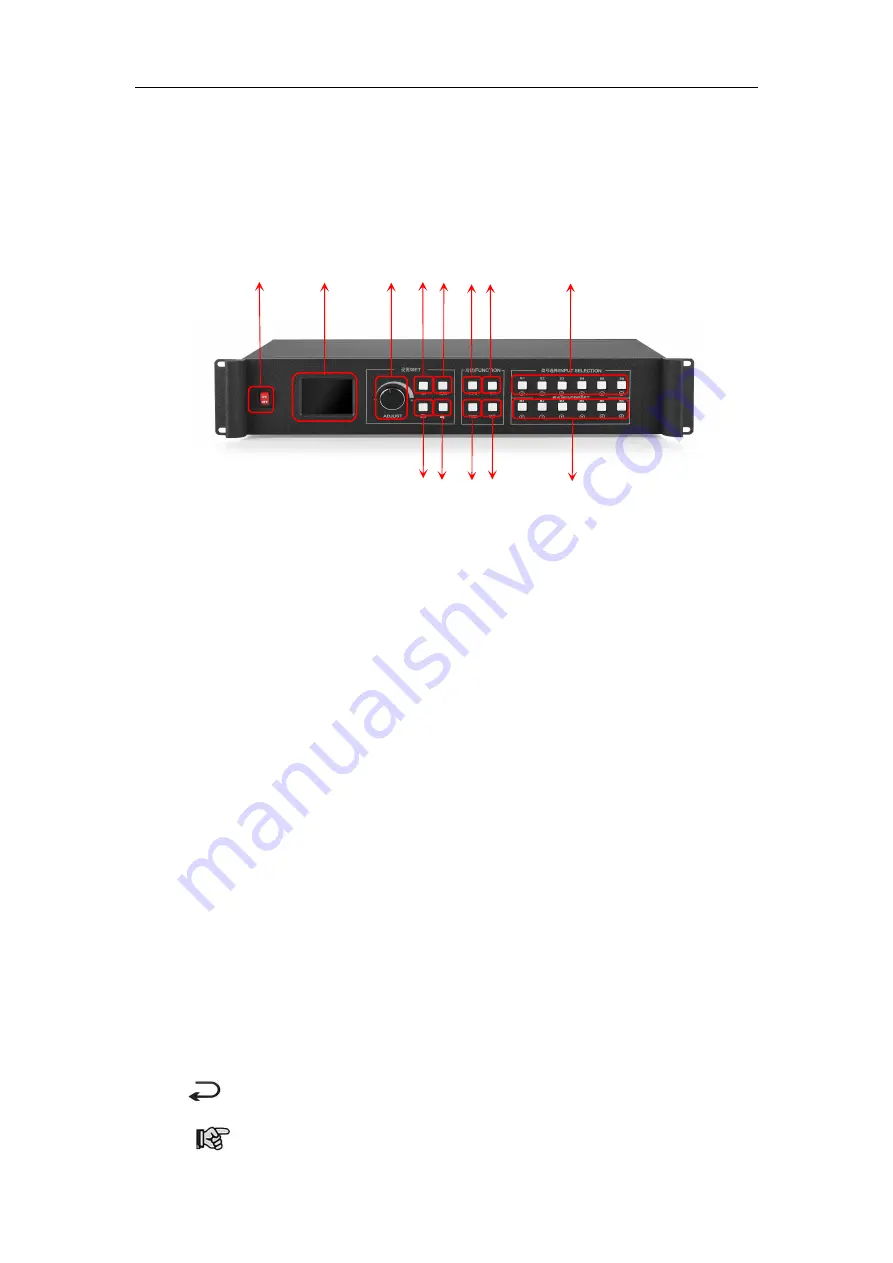
2.1 Front Panel

③ ④⑤ ⑥⑦

⑨⑩

⑪ ⑫

1. POWER:

Power switch of 220V AC. ON indicates power connected, OFF power

disconnected .

2. LCD color screen:

Information display screen showing device information and debugging

information.

3. ADJUST:

Adjusting knob which can be used for selecting information on color screen and

adjusting various parameters rapidly.

Counterclockwise rotation means up and clockwise refers down. Rotation downward

means confirmation.

4. OK:

OK key for confirming debugging information.

5. MENU:

Menu key for access to main menu for device debugging.

6. INFO:

Information query key for real-time condition of input signal.

7. WIN:

Image information key for displaying and switching image signal source.

8. S1-S6:

Signal source key. Signal source key on main menu refers to input source of back

device and that on parameter input interface refers to

number 1 to 5 and backspace key.

9.

:

Back or cancel key.

10.

:

Wizard key. Click for the Wizard Mode.

Содержание KS910P

Страница 1: ...Multi Image Splicing Processor XA Operation Manual ...

Страница 2: ...ingement act Please read the manual carefully before using Any improper operation may cause damage to the product It is operated with electricity and sufficient attention should be attached Our company bears no responsibility for any property loss and personal injury incurred from any improper operation failing to follow the instructions in the manual If the provision herein conflicts with local l...

Страница 3: ...onnel Ensure sound grounding For your safety please ensure that power cable is grounded soundly Keep away from strong magnetic field engine and transformer For normal operation of the device please keep it away from strong magnetic field motor and transformer Guard against damp Keep operational environment dry If the device becomes damping inadvertently do not power the device and use it after bei...

Страница 4: ... 2 2 Back Panel 3 3 Device Debugging 5 3 1 Device Connection 5 3 2 Debugging Procedure 6 3 3 Case explanation 9 3 4 Function Key 15 3 5 Advanced Menu 18 4 Technical Parameters 20 5 FQAs 21 Appendix Graphics copy mode and extended mode setting 23 1 AMD Video Card 23 2 NVIDIA Video Card 24 ...

Страница 5: ...MI CVBS SDI and IP support 4K Ultra HD input and realize large screen point to point display 2 Stand alone can support user defined layout of pixel 10 4 million and support output pixels up to 15360 horizontally or 6144 vertically 3 Support free form six image layout and realize central control of main screen side screen floor tile or canopy of the stage in an easy way 4 Support signal echoing and...

Страница 6: ...nterclockwise rotation means up and clockwise refers down Rotation downward means confirmation 4 OK OK key for confirming debugging information 5 MENU Menu key for access to main menu for device debugging 6 INFO Information query key for real time condition of input signal 7 WIN Image information key for displaying and switching image signal source 8 S1 S6 Signal source key Signal source key on ma...

Страница 7: ... transmitting card into the processor 2 MONTOR Pre monitor channel for monitoring input signal source or output interface information 3 OUTPUT Programmatic output channel for pure digital DVI D output and transmitting card connection 4 LAN1 100MB network control port which can realize device debugging by software with its connection with computer 100MB network interface 5 AC 100 220V Power switch ...

Страница 8: ...hich loops S1 DVI signal and is used for multi machines cascade 9 LAN2 Gigabit network control port which can be used for device debugging and also echoing function 10 COM RS232 control port which connects with computer serial port and can debug device by PC Software ...

Страница 9: ...ransmitting card Large screen Control connection connect computer with device control port and debug device connection method There are three connection methods 1 Connect 100 mbit network control port with splicer LAN1 port which can set device software 2 Connect computer gigabit network port with splicer LAN2 port which can not only set device but also echo signal source image 3 Connect one cryst...

Страница 10: ...orizontally vertical mosaic contents of all outputs are arranged vertically Step 2 select suitable splicing mode and click OK get back to main menu interface to select Screen parameter and enter into its setting interface Set loaded screen point of each output interface and click Confirm after inputting and then screen splice is finished Note there are two ways for number input 1 Adjust by rotate ...

Страница 11: ...t Vertical Size Horizontal Image Layout Image 1 S1 Layout 1 Layout 2 Layout 3 Note In case of signal image skip this step For multi image it s OK if image number and item requirements are in consistent Following operations can be taken when layouts are not consistent Step 4 Click OK and return to main menu interface select Image parameter and enter into its setting interface to set size and positi...

Страница 12: ...Step 6 Click MENU and return to main menu interface select Save setting to enter into Data storage interface select any mode and click OK to save data Note Mode 1 is default startup data of device boot it s suggested that the most common mode or that required by device boot should be saved to Mode 1 At this point basic device debugging is completed If there is other requirement repeat the operatio...

Страница 13: ...is shown as picture below Requirement whole computer desktop should be displayed completely 960 1216 Diagram of loaded transmitting card Display image Debugging Procedure Step 1 click MENU and enter into main menu interface to select Horizontal mosaic of the first item Device mode Note as two transmitting cards are in the 1x2 arrangement horizontal mosaics are needed then Step 2 Click OK to return...

Страница 14: ...en splicing is finished select signal source needed to display on screen and click corresponding key E g for display of computer signal on large screen and connection of computer DVI interface with S1 DVI port of the back device just click S1 in the front which means choosing the signal to display on the screen Step 4 After selecting signal and normal display of large screen save all setting data ...

Страница 15: ...hould be displayed completely 2 Screen is divided into three parts with proportion of 1 2 1 1792 Diagram of loaded transmitting card Display image 1 Display image 2 Debugging Procedure Step 1 Click MENU to enter into main menu interface Select Device mode and then Vertical Mosaic Note as two transmitting cards are in vertical arrangement horizontal mosaics are needed then 704 640 ...

Страница 16: ...ize is 1792 and vertical size 704 for OUT2 they are 1792 and 640 respectively Step 3 After inputting select Confirm and return to main menu interface The large screen splicing is finished select signal source needed to display on screen and click corresponding key E g for display of computer signal on large screen and connection of computer DVI interface with S1 DVI port of the back device just cl...

Страница 17: ... image is displayed completely and correct data are saved For the second requirement which is that screen is divided into three parts with proportion of 1 2 1 only further setting on operation above is needed Step 5 Click MENU and enter into main menu interface and select Image layout then Layout 3 Note Default layout of the device is three equal parts If it is desired there is no need to carry ou...

Страница 18: ... are respectively 1344 and 0 and horizontal and vertical sizes are 448 and 1344 respectively Step 7 According to operation above screen body has been divided into three images with proportion of 1 2 1 Default display content of each image is S1 If different signal sources should be designated for each image click of front panel to enter into image switch interface Select image by rotate knob and c...

Страница 19: ...this key and enter into its interface showing whether all signal sources are inputting normally Its interface is shown as below Red light means signal is lost while green one shows signal is normal WIN Image key Click this key to enter into its interface and signal source selection can be made in the following interface Taking image 3 as instance click WIN to enter into image switch interface whic...

Страница 20: ...t warm backup preview monitor IP setting serial port freeze frame local and global color space input brightness and switch time The following are explanations of those common functions 1 Brightness adjustment The device supports 1 255 stairs brightness adjustment Brightness of all screen body can be adjusted synchronously to meet customers different brightness adjustment requirements for different...

Страница 21: ...sparency adjustment and even point by point adjustment to make application scene more colorful 8 Intelligent warm backup User can set priority of backup signals When current signal fails the system will detect automatically and call backup signal immediately if signal returns to normal the system will call original signal intelligently Parallel system constructed by this function can guarantee rel...

Страница 22: ...es monitoring of output namely large screen display Preview output channel monitor all inputs and outputs Preview input channel monitor signal sources 3 5 Advanced Menu 1 Language Setting Set device language English or Chinese 2 Output resolution Support single output resolution user defined resolution is available and support 30HZ 50HZ and 60HZ frame rates Default output resolution is 1920 1080 6...

Страница 23: ... 6 Multi machine cascade Device cascade mosaic is commonly used to solve device de synchronization 7 Common Functions Click FUNC to get quick access to common settings 8 Technical Support Inquire device version number and its IP address 9 EDID Reset all EDID ports 10 Mode Delete Delete wrongly saved or repeated mode s 11 Keyboard Lock Lock front panel key to avoid misoperation of irrelevant person...

Страница 24: ...0 Plus signal image can be gained on computer at real time by KYSTAR control software which includes both input signal and output signal Warm Backup Users can set priority of input signals When current signal fails the system will output next priority signal automatically When signal returns to normal it will turn back Image text and Caption Overlay Users can add text or pictures on video screen a...

Страница 25: ...e is normally desktop laptop VOD and Matrix CV Composite video signal also called composite video which can pack all signals together and transfer it as a whole Its signal source is normally camera DVD Cable Box VOD and video matrix Q2 Please give a brief introduction of the connection method of graphics splicer transmitting card receiving card and LED A Connect graphics DVI VGA output port with s...

Страница 26: ... of serial port Two or more software windows are not allowed to be open simultaneously Failure of serial port line connection or damage of the line Damage of COM drive of the board or serial port If suggestions above fail to solve your problems at last please contact our customer service in time We will help you to solve your problems as soon as possible Q6 What are the possible reasons for networ...

Страница 27: ...Processor 23 Appendix Graphics copy mode and extended mode setting 1 AMD Video Card Right click on blank space of the desktop Property Setting Advanced enter into Graphics Drive Control Board Right click Copy Extended mode ...

Страница 28: ...Multi Image Splicing Processor 24 2 NVIDIA Video Card Right click on blank space of the desktop Property Setting Advanced Enter into Graphics Drive Control Board Right click Copy Extended mode ...

Страница 29: ...Multi Image Splicing Processor 25 ...

Отзывы: