background image

A-7

FS-1010

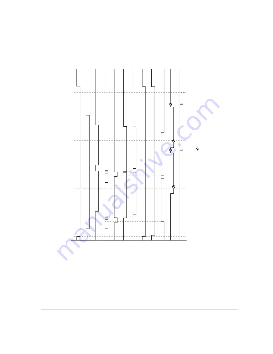
5. MP tray feeding, two legal size papers

MO

T

O

RN

(Main motor)

MHVDR

(Main charger)

THVDR

(T

ransf

er charger)

MPFSOL

(MP f

eed clutch)

RESDRN

(Registr

ation clutch)

OUTPEN

(Laser diode)

BIAS

(De

v

eloping bias)

ERASPW

(Er

aser lamp)

PLGDRN

(P

olygon motor)

RESIT

(Registr

ation sensor)

EXITN

(Exit sensor)

COUNT

(T

otal counter)

0 (s)

5

10

15

800

800

2588

5607

7395

11580*

7061

15627

15627

10830

8677

9251

9965

13771

8964

12592

15627

6534

6845

6773*

6213

VSREQ (6716)

11413*

11418

6023

2038

1727

1406

VSREQ(1909)

2254

1538

4444

5158

100

1909

1909

1909

*:

 V

a

ries depending on paper siz

e

.

 :

 J

a

m detection timing

Dr

um speed:

 84.00 mm/s

P

aper f

eeding speed:

 84.00 mm/s

Pr

inting speed:

 12.14 ppm

6716

6716

6345

6716

13484

6641

6606*

Содержание Ecosys FS-1010

Страница 1: ...SERVICE MANUAL Published in Dec 01 Laser printer...

Страница 2: ...Version Replaced pages Remarks Date 1 0 Revision history 5 Dec 2001...

Страница 3: ...sonnel to ensure the safety of their customers their machines as well as themselves during maintenance activities Service personnel are advised to read this booklet carefully to familiarize themselves...

Страница 4: ...ompliance with warning messages using this symbol WARNING Serious bodily injury or death may result from insufficient attention to or incorrect compliance with warning messages using this symbol CAUTI...

Страница 5: ...or dusty place This may cause fire or electric shock Do not install the printer near a radiator heater other heat source or near flammable material This may cause fire Allow sufficient space around t...

Страница 6: ...clean Dirt on them can cause abnormally high temperatures Do not remove the ozone filter if any from the printer except for routine replacement 2 Precautions for Maintenance WARNING Always remove the...

Страница 7: ...t all the caution labels that should be present on the machine according to the instruction handbook are clean and not peeling Replace with new ones if necessary Handle greases and solvents with care...

Страница 8: ...2 3 Using the operator panel 2 15 Chapter 3 3 1 Maintenance Adjustments 3 3 Chapter 4 4 1 Electrophotographic system 4 3 4 2 Paper feeding system 4 15 4 3 Electrical control system 4 18 Chapter 5 5 1...

Страница 9: ...Chapter 1 P r o d u c t I n f o r m a t i o n...

Страница 10: ...Laser safety 1 7 2 Laser notice 1 7 3 Laser caution label on the scanner unit 1 7 4 CDRH regulations U S A 1 9 5 Ozone concentration 1 9 6 Optional equipment 1 9 7 Important note on the interface conn...

Страница 11: ...ckness Capacity of output trays 80 g m2 0 11 mm thickness Electrophotography laser scan 14 pages min A4 15 pages min Letter Fast 1200 mode 1800 horizontal 600 vertical 600 horizontal 600 vertical KIR...

Страница 12: ...MB Optional KPDL2 Upgrade kit 16 MB Standard equipped on main board Maximum 144 MB Including the standard 16 MB main RAM Accepts any of 16 32 64 128 MB DIMM Parallel High speed bidirectional IEEE1284...

Страница 13: ...2 7 1 A U S A Canada Normal operation 265 W Maximum 818 W Standby 13 W Sleeping 5 W 220 to 240 V model 6 W 120 V model Item Specification Item S Operating temperature and humidity Maximum altitude No...

Страница 14: ...e of parts 1 Top cover 2 Face down output tray 3 Face up output tray 4 Side cover 5 Operator panel 6 Front cover 7 Paper cassette 8 MP tray 9 Option interface slot cover 0 Parallel interface connector...

Страница 15: ...the printer is completely confined within protective housings and external covers the laser beam cannot escape from the printer during any phase of user operation 2 Laser notice This printer is certi...

Страница 16: ...mance of procedures other than those specified herein may result in hazardous radiation exposure Figure 1 3 1 Caution labels Label on the scanner unit Inside the printer Label on the left cover rear s...

Страница 17: ...of installation and cause an unpleasant smell To minimize concentration of ozone gas to less than 0 1 ppm we recommend you not to install the printer in a confined area where ventilation is blocked 6...

Страница 18: ...n unstable cart stand or table Near an AC wall outlet preferably one that can be used for the printer alone The outlet should have a ground slot or an adapter should be used If you use an extension co...

Страница 19: ...earance on all sides of the printer as diagrammed below Figure 1 4 2 Clearances Ref Clearance Dimensions 1 Left 25 cm 9 7 8 inches 2 Front 50 cm 19 11 16 inches 3 Right 25 cm 9 7 8 inches 4 Back 40 cm...

Страница 20: ...not use other power sources Disconnect the printer from the power source before attempting removal or replacement of an electrical component or a printed circuit board The printer should not be connec...

Страница 21: ...ner process unit and the supplies should be removed from the vehicle The vehicle during transportation should be parked in the shade or with the window open to allow minimum air circulation or the ade...

Страница 22: ...ry toner Kyocera do not recommend to use any refilled toner containers that may be available commercially This is because Kyocera have no means of control over how such refilled toner could affect the...

Страница 23: ...isfies the following environmental conditions Temperature 20 to 40 C 4 to 104 F Humidity 15 to 90 RH NOTE If the toner container is removed from the printer s developer unit put it in a protective bag...

Страница 24: ...Chapter 2 Installation Operation...

Страница 25: ...nding memory 2 8 1 Minimum memory requirements 2 8 2 DIMM specifications 2 8 3 Notes on handling DIMM 2 9 4 Installing the DIMM 2 10 5 Testing the expansion memory 2 11 6 Installing the memory card Co...

Страница 26: ...a flat stable surface Remove the manuals toner kit and other items located on top of the spacer and remove the spacer Carefully remove the printer Figure 2 1 1 Unpacking 1 Remove the tape on the rear...

Страница 27: ...gin installation with connecting the printer and the paper feeder For details refer to the optional Paper feeder s Service Manual 2 2 1 Installing the toner container 1 Open the top cover all the way...

Страница 28: ...e seal 3 orange colored facing up Shake the toner container 2 horizontally at least five times This ensures that the toner is evenly distributed inside Figure 2 2 2 Shaking the toner container 4 Caref...

Страница 29: ...2 6 FS 1010 5 Install the toner container 2 into the printer 6 Push firmly on the top of the toner container 2 at the positions marked PUSH HERE Figure 2 2 4 Installing the toner container 2...

Страница 30: ...in the manner above there will be a delay of several minutes before the printer gets ready to print a job This delay is necessary for the printer to fill the developer reservoir with a sufficient amou...

Страница 31: ...MB 1 Minimum memory requirements Refer to the table below for minimum memory requirements in various environments Resolution Printing environment Emulation 300 dpi 600 dpi HP LaserJet 5P factory setti...

Страница 32: ...otect the electronics by taking these precautions Before touching a DIMM touch a water pipe or other large metal object to discharge yourself of static electricity While doing the work it is recommend...

Страница 33: ...uch as metal chips or liquid get inside the printer during the installation process Operation of the printer during the presence of a foreign substance may lead to fire or electric shock WARNING Turn...

Страница 34: ...he DIMM Figure 2 2 8 Inserting the DIMM 5 Testing the expansion memory After installing DIMM in the printer test the printer to see if the installation has been successful To test the expansion memory...

Страница 35: ...able and disconnect the printer from the computer or the network Never insert or remove a memory card while the printer power is ON Failure to turn the power switch OFF will immediately halt the print...

Страница 36: ...emory card 4 in the slot Insert as shown in the figure Push it in all the way Close and secure the option interface slot cover or network interface card or the serial Interface board Figure 2 2 10 ins...

Страница 37: ...lectric shock WARNING Turn the printer s power switch off Unplug the printer s power cable and disconnect the printer from the computer or the network Never insert or remove a network interface card w...

Страница 38: ...nel function No Name Function 1 On line indicator 2 Data indicator 3 Paper empty Paper jam indicator 4 Toner indicator 5 Cancel key 6 Go key Indicates whether the printer is on line or off line Indica...

Страница 39: ...ELP button 5 GO button 6 MENU button 7 Monitor window Indicates printer status the interface currently active the resolution the paper size the number of copies set in the current interface and error...

Страница 40: ...Chapter 3 Maintenance Adjustments...

Страница 41: ...iner 3 4 3 Toner container replacement 3 5 4 Toner saver mode EcoPrint 3 6 3 1 3 Cleaning the printer 3 7 1 Cleaning the registration roller 3 8 2 Cleaning the main charger wire 3 8 3 1 4 Updating the...

Страница 42: ...nominal life expectancy for modules Detailed part information for each module except toner container can be found in Parts Catalog Table 3 1 1 Life expectancy of modules Kit Module Nominal life pages...

Страница 43: ...toner the Toner indicator flashes on the operation panel Be sure to promptly replace the toner container and clean the inside of the printer when this message appears If the printer stops printing wh...

Страница 44: ...tainer open the top cover Pull lock lever 1 1 to the release UNLOCK position then pull lock lever 2 2 to the release right position Figure 3 1 1 Releasing Lock levers 1 and 2 Gently remove the old ton...

Страница 45: ...h the instructions provided in chapter 2 Installing the toner container on page 2 4 to complete installation of the new toner container 4 Toner saver mode EcoPrint The EcoPrint enables to reduce the a...

Страница 46: ...the printer first remove the process unit from the printer Open the top cover 1 and front cover 2 Lift the process unit 3 together with the toner container out of the printer Figure 3 1 4 Removing the...

Страница 47: ...ng the registration roller 2 Cleaning the main charger wire Slide the charger cleaner knob green colored back and forth 2 to 3 times then return it to its CLEANER HOME POSITION 1 1 Figure 3 1 6 Cleani...

Страница 48: ...message in different languages can also be downloaded through the parallel interface or through the memory card CompactFlash 1 Firmware program data format Kyocera supplies the following types of dat...

Страница 49: ...nected to the printer with a parallel cable 1 Turn printer power on Make sure the printer is ready 2 At the DOS prompt send the following command to the printer echo R UPGR SYS EXIT prn DOS COPY b the...

Страница 50: ...the two screws and then remove the slot cover Insert the memory card in the printer s memory card slot 3 Turn power switch on 4 The printers starts and finishes downloading automatically 5 Confirm th...

Страница 51: ...lel cable Improper connection of parallel cable between PC and printer Check the contact between PC and printer s interface connector Confirm whether the firmware conforms to this printer Replace the...

Страница 52: ...Chapter 4 O p e r a t i o n O v e r v i e w...

Страница 53: ...4 Transfer 4 11 5 Fusing 4 12 Fuser unit mechanism 4 13 6 Cleaning 4 14 4 2 Paper feeding system 4 15 4 2 1 Paper feed control 4 16 Paper feeding mechanism 4 17 4 3 Electrical control system 4 18 4 3...

Страница 54: ...echnical details on the printer s electrophotography system 4 1 1 Electrophotographic cycle The electrophotography system of the printer performs a cyclic action made of six steps as follows Each step...

Страница 55: ...ear Z18 Z35H 0 MAG gear Z24H Mixer gear Z20 B Mixer gear Z20 A DLP screw B DLP screw A Drum Drum gear Z35H Drum shaft Drum gear Z36 Sweep gear Z13 Idle gear 18H Cleaning blade Sweep roller Waste toner...

Страница 56: ...h as a screwdriver etc resulting in a print quality problem Also finger prints can cause deterioration of the OPC layer therefore the drum in the process unit must be handled with care Substances like...

Страница 57: ...e layer is given a uniform positive corona charge dispersed by the main charger wire B Due to high voltage scorotron charging the charging wire can get contaminated by oxidization after a long rum The...

Страница 58: ...canner unit B Figure 4 1 5 Exposure The laser beam 780 nm wavelength beam is dispersed as the polygon motor polygon mirrors revolves to reflect the laser beam over the drum Various lenses and mirror a...

Страница 59: ...esponding to one scanned line width on the drum when laser beam scans on it 4 F theta lens The f theta lens equalizes focusing distortion on the far ends of the drum 5 Sensor mirror Bends the very fir...

Страница 60: ...lectrical resistance of the photoconductor is reduced and the potential on the photoconductor is also lowered Resulted on the drum surface is an electrostatic image which represents the data to print...

Страница 61: ...The developing roller A is applied with the AC weighted positive DC power source Toner E on the developing roller A is given a positive charge The positively charged toner E is then attracted to the...

Страница 62: ...and the transfer roller Figure 4 1 9 Transfer The nominal transfer bias is set to approximately 1 8 kV limit with the 6 A current Since the ideal potential of the transfer bias depends on the thickne...

Страница 63: ...a long run Care must be taken while handling the heat roller not to scratch the roller surface as doing so may result in print problems The heat roller has four claws which are continuously in contact...

Страница 64: ...34 3 Exit gear Z23 4 Idle gear Z18 0 1 2 3 4 5 6 7 8 9 5 Heat gear Z33 6 Press roller 7 Heater lamp 500 25 W 8 Thermal cutout 9 Separator s 0 Thermistor Exit pulley s Lower exit roller Fuser unit mech...

Страница 65: ...back to the toner container into the waste toner reservoir D Figure 4 1 12 Drum cleaning and erasing static charge After the drum B is physically cleaned it then must be cleaned to the electrically n...

Страница 66: ...up tray as manipulated by the user The figure below shows the components in the paper feeding system and the paths through which the paper travels The sensors clutches etc are described in the follow...

Страница 67: ...utch MP feed clutch Registration sensor Registration clutch Engine board Main motor EXITN MOTORN RESDRN RESIT PAPERN MPFDRN FEDDRN HANDSN YC11 8 YC12 9 YC09 2 YC04 1 YC07 2 YC04 8 YC03 2 YC12 7 1 MP f...

Страница 68: ...1 Main motor gear 2 Registration clutch 3 MP feed clutch 4 Feed clutch 5 MP feed roller 6 Feed roller 7 Registration gear Z13 8 Registration gear Z20 9 Cassette gear 0 Lower registration roller Upper...

Страница 69: ...aper jam indicator LED E Data indicator LED F On line indicator LED 6 Main motor 7 Cooling fan 8 Registration clutch 9 Feed clutch 0 MP feed clutch MP paper sensor Toner sensor Waste toner sensor Eras...

Страница 70: ...K PBUSY PPERROR PSELECT PFAULT PPDATA7 0 YC05 PDATA7 0 NSELIN Option serial I F P1284DIR DTR RTS TXD CTS DSR RXD RSSEL YC09 DBTXD DBRXD DBCLK Debugger connector U9 3 3 V Regulator 5 V1 3 3 V1 SDRAM Da...

Страница 71: ...toner sensor Exit sensor Interlock switch Heater lamp Thermistor Cooling fan High voltage output circuit MHVDR THVDR RTHDR HVISEL HVCLK Regist ration sensor Paper sensor MP paper sensor 5 V DC output...

Страница 72: ...l after one second If the eraser lamp is normal the current flowing through R74 also flows the zener diode DZ01 making the voltage at pin 27 to be approximately 3 7 V On the contrary if the level at p...

Страница 73: ...of alternating plus and negative current and detects the zero crosses This detector derives the resultant ZCROSS signal at its pin 43 of the engine CPU U01 Since abrupt change in the current flow can...

Страница 74: ...d for the 6 positive and negative envelops out of 10 The duty cycle is 0 since the heater lamp is kept turned off for the whole envelops CPU U01 selectively switches among those variations for applyin...

Страница 75: ...On On On On On On On On On On On Off Off On On Off On On Off On On Off Off On Off Off Off Off Off Off Off Off Off Off Off Off On Off Off On On Off Off Variation No 4 Duty 40 Variation No 5 Duty 0 Heat...

Страница 76: ...the polygon motor is revolving at the rated speed turns PLGDRN to L level to acknowledge the engine CPU that the rated speed has been achieved On the contrary if PLGRDYN does not turn to L level withi...

Страница 77: ...ver current detection circuit Power switch Current fuse Noise filter circuit Transformer T1 24 V DC rectifier smooth ing circuit 24 V DC shutoff circuit Over voltage detection circuit Photo coupler PC...

Страница 78: ...the toner sensor Figure 4 3 9 Bias board circuit block diagram Developing roller Bias board KP 884 Engine board Regist ration sensor Developing bias output circuit FANL FAN FANH PAPERN SWIN RESIT TONE...

Страница 79: ...nd the engine board Figure 4 3 10 High voltage board circuit block diagram Control and driver circuit Transfer bias output positive voltage circuit MHVDR THVDR RTHVDR PSEL1 PSEL2 HVISEL 24V2 24V2 24V1...

Страница 80: ...the power supply board is disconnected deactivating the high voltage output laser output main motor output for safety The cooling fan is an exception Since the cooling fan is directly fed with 24 V DC...

Страница 81: ...Chapter 5 D i s a s s e m b l y...

Страница 82: ...ansfer roller 5 10 5 2 6 Removing the principal circuit boards 5 11 1 Removing the engine board 5 11 2 Removing the main board 5 12 3 Removing the power supply board and high voltage board 5 14 4 Remo...

Страница 83: ...listed in the Ecosys Screw catalog These screw symbol numbers are universal to most Ecosys printers CAUTION When securing a self tapping screws align it with the thread carefully First turn it counter...

Страница 84: ...the front cover 2 3 Lift the process unit 3 together with the toner container out of the printer Figure 5 2 1 Removing the process unit CAUTIONS After removing the process unit seal it in the protect...

Страница 85: ...he principal outer covers 1 Removing the top cover face down output tray 1 Open the top cover 1 2 Remove two screws 2 3 Remove the top cover face down output tray 3 Figure 5 2 2 Removing the top cover...

Страница 86: ...six snaps 3 and one hook hole 4 on the chassis remove the right cover 5 Figure 5 2 3 Removing the right cover 3 Removing the left cover 1 Unlatch the six snaps 1 and two hook holes 2 on the chassis re...

Страница 87: ...r fit the D cut shaft into the D shape hole of the feed roller 1 Remove the paper cassette and the process unit See page 5 4 2 Stand the machine the front side up 3 Move the feed roller in the directi...

Страница 88: ...ing the MP tray feed roller 1 Remove the engine board See page 5 11 2 Remove one screw 1 3 Remove the grounding plate 2 4 Remove one stop ring 3 5 Remove the MP feed clutch 4 Figure 5 2 6 Removing the...

Страница 89: ...pring 7 8 Remove two screws 8 9 While pressing the latch 9 by using the driver and then remove the MP feed unit 0 Figure 5 2 7 Removing the MP feed unit 10 Remove the stop ring and then remove the MP...

Страница 90: ...e bushes and springs make sure to refit the black colored bush and spring on the left side Also observe the correct direction to which the bush is fit in reference to the paper passing direction 1 Rem...

Страница 91: ...Removing the engine board 1 Remove the top cover face down output tray and right cover See pages 5 5 and 5 6 2 Remove all ten connectors from the engine board 1 3 Remove three screws 2 4 Remove the e...

Страница 92: ...page 5 4 2 Remove the top face down output tray and right cover See pages 5 4 and 5 5 3 Remove two connectors 1 from main board 2 4 Remove six screws 3 5 Remove the controller box with main board 4 F...

Страница 93: ...6 Remove two screws 5 at the back of the main board 2 7 Remove three screws 6 from the parallel interface connector 7 and USB connector 8 8 Remove the main board 2 Figure 5 2 12 Removing the main boa...

Страница 94: ...ges 5 5 and 5 6 3 Remove three connectors 1 from the power supply board 2 4 Remove eight screws 3 5 Remove the power supply board 2 and high voltage board 4 Note The high voltage board 4 is directly c...

Страница 95: ...s 5 5 and 5 6 3 Remove the power supply board and high voltage board See the previous page 4 Stand the machine with the front side up 5 Remove one connector 1 from the bias board 2 6 Remove five screw...

Страница 96: ...the cassette and process unit See page 5 4 2 Remove the top cover face down output tray and right cover See pages 5 5 and 5 6 3 Remove three connectors 1 from the main motor 2 4 Remove four screws 3 5...

Страница 97: ...FS 1010 5 17 5 2 16 Removing the cord cover 6 Remove the engine board See page 5 11 7 Remove wires from wire saddles 4 on the cord cover 5 8 Remove one screw 6 9 Remove the cord cover 5 6 4 4 5...

Страница 98: ...10 5 18 10 Remove one screw 6 11 Remove the grounding plate 7 12 Remove three stop rings 8 13 Remove MP feed clutch 9 feed clutch 0 and registration clutch Figure 5 2 17 Removing the clutches 8 7 8 9...

Страница 99: ...FS 1010 5 19 14 Remove the four screws 15 Remove the drive unit Figure 5 2 18 Removing the drive unit...

Страница 100: ...and the printer s drive gear are properly meshed with each other For this rotate the main motor several turns before fixing screws 1 Remove the process unit See page 5 4 2 Remove the top cover face do...

Страница 101: ...FS 1010 5 21 7 Remove two screws 5 8 Open and split the fuser unit 4 Figure 5 2 20 Splitting the fuser unit 5 5 4...

Страница 102: ...er the printer was running Allow substantial period of time until it cools down 1 Remove and split the fuser unit See page 5 20 2 Loosen the stopper screws 1 3 Hold the separators 2 upright and remove...

Страница 103: ...vent proper fusing of toner on paper When holding the heater lamp hold the ceramic parts of heater lamp at both ends When refitting the heater lamp direct the short distance side from the projection i...

Страница 104: ...Allow substantial period of time until it cools down 1 Remove and split the fuser unit See page 5 20 2 Remove the heater lamp See previous page 3 Press the lamp A holder 1 away from the heat roller P...

Страница 105: ...FS 1010 5 25 3 Remove the heat gear Z33 4 heat R bush 2 and heat L bush 3 from the heat roller 5 Figure 5 2 24 Removing the heat roller 2 3 4 5...

Страница 106: ...thermistor 1 Remove and split the fuser unit See page 5 20 2 Remove the heater lamp See page 5 23 3 Remove the heat roller See page 5 24 4 Remove one screw 1 5 Remove the thermistor 2 Figure 5 2 25 R...

Страница 107: ...the terminals of the thermal cutout 1 Remove and split the fuser unit See page 5 20 2 Remove the heater lamp See page 5 23 3 Remove the heat roller See page 5 24 4 Remove the two screws 1 5 Remove the...

Страница 108: ...oller is extremely hot immediately after the printer was running Allow substantial period of time until it cools down 1 Remove and split the fuser unit See page 5 20 2 Remove the press roller 1 from t...

Страница 109: ...5 4 2 Remove the top cover face down output tray right cover and the left cover See pages 5 5 and 5 6 3 Remove four connectors 1 4 Remove five screws 2 and four screws 3 5 While keeping the ground joi...

Страница 110: ...FS 1010 5 30 5 Remove three screws 6 6 Remove one connector 7 from the laser scanner unit 8 7 Remove the laser scanner unit 8 Figure 5 2 27 Removing the laser scanner unit 6 7 8...

Страница 111: ...FS 1010 5 31 8 Remove the eraser lamp 9 9 5 2 28 Removing the eraser lamp...

Страница 112: ...aps 1 and remove the main charger cap 2 3 Draw the main charger unit 3 in the direction of arrow A then pull it out in the direction of arrow B 5 2 29 Removing the main charger unit CAUTION When refit...

Страница 113: ...Chapter 6 T r o u b l e s h o o t i n g...

Страница 114: ...7990 Waste toner full Total page count more than 100 000 pages of printing 6 18 8 F010 Controller checksum error 6 18 9 F020 Controller RAM read write error 6 18 10 F030 Controller system error 6 19 1...

Страница 115: ...its top The indicators are lit fast flashing slow flashing and off in combination to describe a specific message The following diagram depicts these indicators and the control keys Figure 6 1 1 Indic...

Страница 116: ...cribe whether the indicator is lit fast flashing slow flashing or off By using the Remote Operation Panel utility to monitor the printer s status from the computer the error message can be is displaye...

Страница 117: ...ng data The printer is waiting for the end of job command before printing the last page Pressing the Cancel key allows you to obtain the last page immediately The printer is printing the last page aft...

Страница 118: ...the paper source The printer prints on the paper size and type set in that particular paper source The cassette paper size and data paper size are not the same The printer feeds from the MP Tray when...

Страница 119: ...age 3 4 There is no paper in the MP tray Add paper to the tray Press the Go key to resume printing Note Feeding the paper having a paper size which does not match the current paper size from the MP tr...

Страница 120: ...ry for use by memory card Expand printer memory Press the Go key to resume printing You can abandon printing by pressing the Cancel key Printing cannot continue because there is not enough memory Try...

Страница 121: ...gain 02 RAM disk mode is Off Turn RAM disk mode On 04 No disk space Clean up files 05 Specified file is not on disk 06 No memory for use by disk system Expand printer memory Continued on next page The...

Страница 122: ...er switch off then on Connect oscilloscope to pin 8 MOTORN and pin 7 MRDYN of CN1 on main motor Does pin 8 MOTORN of YC04 on engine board KP 882 goes high then low 24 V DC at pin 9 of CN1 on main moto...

Страница 123: ...onds after pin 3 PLGDRN goes high then low Call service 4000 nnnnnn Replace engine board KP 882 See page 5 11 Replace harness S02779 between engine bard and laser scanner unit Replace harness S02779 b...

Страница 124: ...er switch on Replace harness S02770 between engine board and main board Replace engine board KP 882 See page 5 11 OK Yes Yes Turn power switch on OK End End A Continued from previous page Replace main...

Страница 125: ...cond after pin 4 OUTPEN goes high then low Call service 4200 nnnnnn Replace harness S02770 between main board and engine board Yes Replace main board KP 888 See page 5 12 Replace main board KP 888 See...

Страница 126: ...5 11 No OK Replace engine board KP 882 See page 5 11 Replace main board KP 888 See page 5 12 No Turn power switch on OK Yes Yes End End C Continued from previous page Replace main board KP 888 See pa...

Страница 127: ...ASPW of YC05 on engine board KP 882 output 24 V DC before shown 5300 error Does pin 2 ERASER of YC05 on engine board KP 882 remain low Turn power switch off then on Print a status page Call service 53...

Страница 128: ...e thermal cutout or heater lamp See page 5 26 or 5 23 Replace bias board or high voltage board or power supply board See page 5 15 or 5 14 Call service 6000 nnnnnn Open infinite No No Open infinite Me...

Страница 129: ...ke the process unit horizontally Turn power switch off then on Replace the process unit 7980 error shown Turn power switch off then on Call service 7980 nnnnnn End Printer indicators 7980 error shown...

Страница 130: ...Replace the waste toner sensor or engine board KP 882 See page 5 11 8 F010 Controller checksum error Turn power switch off then on If not solved replace main board See page 5 12 9 F020 Controller RAM...

Страница 131: ...t solved replace engine board See page 5 12 or main board See page 5 12 12 F050 Engine ROM checksum error Turn power switch off then on If not solved replace engine board See page 5 12 Printer indicat...

Страница 132: ...elow ABC 123 ABC 123 ABC 123 ABC 123 1 Completely blank printout See page 6 21 2 All black printout See page 6 22 3 Dropouts See page 6 23 5 Black horizontal streaks See page 6 24 7 Unsharpness See pa...

Страница 133: ...transfer bias output on the high voltage board This requires removal of the left cover and the test equipment Replace the high voltage board if high voltage potential is not available on the board See...

Страница 134: ...terminal between the process unit and the printer main unit Check the drum bias Make sure the bias from the high voltage board correctly arrives at the process unit Check high voltage potential at the...

Страница 135: ...place the press roller or heat roller See page 5 28 or 5 14 Check paper for property Paper with rugged surface or dump tends to cause dropouts Replace paper with the one that satisfies the paper speci...

Страница 136: ...defects occur at random intervals the toner may be leaking from the process unit Replace the process unit 5 Black horizontal streaks Check the process unit s ground of the process unit The drum axle...

Страница 137: ...leaning knob in and out several times Check the drum surface for a streak of toner laying lengthwise A streak of toner remaining on drum after printing means that the cleaning blade in the process uni...

Страница 138: ...ller if necessary See page 5 10 Check the transfer bias potential Check the transfer bias output on the high voltage board This requires removal of the left cover and the test equipment Replace the hi...

Страница 139: ...oximately 400 V This may vary depending on production lots Measurement is possible only by using the jig and tool specifically designed for this purpose The drum unit will have to be replaced if it be...

Страница 140: ...such parts as the paper chute paper transportation paths the bottom of the process unit and the fuser unit inlet Clean these areas and parts to remove toner Check the transfer roller If the transfer...

Страница 141: ...n the printed page See the above section for details Figure 6 1 2 Repetitive defects gauge First occurrence of defect 63 mm Developing roller Process unit 25 mm Upper registration roller 38 mm Lower r...

Страница 142: ...remove the jammed paper as described below After you have removed the jammed paper open and close the top cover once 1 Jam at the face down and face up trays 1 Open the face up tray and remove the ja...

Страница 143: ...e and remove the jammed paper Figure 6 1 4 Jam at the paper cassette 3 Jam inside the printer 1 Open the top cover and front cover 2 Take the process unit together with the toner container out of the...

Страница 144: ...Appendix A D i a g r a m s...

Страница 145: ...ze papers A 3 2 Option paper cassette feeding two legal size papers A 4 3 Option paper cassette feeding two letter size papers A 5 4 MP tray feeding two A4 size papers A 6 5 MP tray feeding two legal...

Страница 146: ...mp PLGDRN Polygon motor RESIT Registration sensor EXITN Exit sensor COUNT Total counter 0 s 5 10 15 800 800 2499 4910 6609 10097 9965 6275 14144 14144 9347 7891 8465 9179 12288 8178 11109 14144 5748 5...

Страница 147: ...RN Polygon motor RESIT Registration sensor EXITN Exit sensor COUNT Total counter 0 s 5 10 15 800 800 2499 5607 7306 11491 11359 6972 15538 15538 10741 8588 9162 9876 13682 8875 12503 15538 6445 6684 6...

Страница 148: ...LGDRN Polygon motor RESIT Registration sensor EXITN Exit sensor COUNT Total counter 0 s 5 10 15 800 800 2499 4700 6399 9677 9545 6065 13724 13724 8927 7681 8255 8969 11868 7968 10689 13724 5538 5777 5...

Страница 149: ...IT Registration sensor EXITN Exit sensor COUNT Total counter 0 s 5 10 15 800 800 2588 4910 6698 10186 10054 6364 14233 14233 9436 7980 8554 9268 12377 8267 11198 14233 5837 6148 6076 5516 VSREQ 6019 1...

Страница 150: ...SIT Registration sensor EXITN Exit sensor COUNT Total counter 0 s 5 10 15 800 800 2588 5607 7395 11580 7061 15627 15627 10830 8677 9251 9965 13771 8964 12592 15627 6534 6845 6773 6213 VSREQ 6716 11413...

Страница 151: ...RESIT Registration sensor EXITN Exit sensor COUNT Total counter 0 s 5 10 15 800 800 2588 4700 6488 9766 9634 6154 13813 13813 9016 7770 8344 9068 11957 8057 10778 13813 5627 5938 5866 VSREQ 5809 9599...

Страница 152: ...10 B10 A11 B11 A12 B12 A1 B1 A2 B2 A3 B3 A4 B4 A5 B5 A6 B6 A7 B7 A8 B8 A9 B9 A10 B10 A11 B11 A12 B12 1 2 3 4 5 6 7 8 1 2 3 4 5 6 7 8 1 2 3 4 5 1 2 3 4 5 1 2 3 4 5 1 2 3 4 5 1 2 3 4 5 6 7 8 9 10 11 12...

Страница 153: ...Appendix B S t a t u s P a g e...

Страница 154: ...Appendix B Contents Status page B 3 Printing the service status page B 3 Details of service information B 4...

Страница 155: ...To print a service status page proceed as follows Printing the service status page To print a service status page using the Go key on the operator panel Or have a PC running MS DOS and proceed as foll...

Страница 156: ...ed on the next page Details of service information Software version Released 23 July 2001 Controller firmware version Released date of the firmware Service information Service information A003 28 00C...

Страница 157: ...page 9690 t P00 S00 F00 N00 0020 0020 1061 8811 0 0 0 RS2 00 AI E G 1 0200800000000000 0000000000000000 00000000000E1000 0000000000000000 00800080 00800080 00800080 80000000 00000000 00000000 00000000...

Страница 158: ...erage print coverage total Calibration table setting bit 7 0 No error with bidirectional communication 1 Error with bidirectional communication bit 6 0 No ECP communication 1 ECP communication had occ...

Страница 159: ...slot 1 Serial number for the printer Two digits for integer part one digit for decimal unit is in percent B Level 1 Less than 0 5 C Level 2 0 6 to 1 0 D Level 3 1 1 to 2 0 E Level 4 2 1 to 3 0 F Level...

Страница 160: ...Appendix C I n t e r f a c e...

Страница 161: ...USB interface pin assignment C 6 Serial interface Optional C 7 Changing the serial interface configuration C 7 Serial interface signals C 9 RS 232C interface voltage levels C 9 RS 422A interface volt...

Страница 162: ...by commanding Prescribe commands on a PC Selecting the parallel interface mode To change the parallel interface mode a PC running MS DOS is needed Connect the printer to the PC via the parallel interf...

Страница 163: ...und GND 5 Data4 PAD3 23 Ground GND 6 Data5 PAD4 24 Ground GND 7 Data6 PAD5 25 Ground GND 8 Data7 PAD6 26 Ground GND 9 Data8 PAD7 27 Ground GND 10 nAck ACKOUT 28 Ground GND 11 Busy BUSYOUT 29 Ground GN...

Страница 164: ...nals are not used unless enabled by the FRPO command O2 parameter This signal is used in the Epson version of the Centronics interface to receive a carriage return In high speed mode it is used as an...

Страница 165: ...ds Connectors Printer B type receptacle female with upstream port Cable B type plug male Cable Use shielded cable that complies with the USB Revision 1 1 standards and not longer than 5 meters 16 feet...

Страница 166: ...th these models To change the serial interface protocol refer to Changing the serial interface configuration section which follows A 25 pin D sub connector is used for the serial interface The extra s...

Страница 167: ...e the serial protocol from RS 232C to RS 422A for example carefully remove the jumper connector 3 on the serial interface board 2 Reconnect to the pin position as shown in the diagram Replace the seri...

Страница 168: ...9 This output transmits asynchronous inverted form of differential data from the printer to the computer SDB Pin 8 10 This output carries asynchronous non inverted form of differential data from the...

Страница 169: ...er serial port DB 25 Printer serial port DB 25 Connector configurations The printer uses a DB 25 connector for the serial interface Depending on the computer configurations for serial interface use ei...

Страница 170: ...manufacture s instruction Since the RS 422A configuration does not employ control lines except for data transmission reception select a mode in which signals such as DTR are not used Protocol The ser...

Страница 171: ...Japan Phone 06 6764 3555 KYOCERA MITA EUROPE B V Hoeksteen 40 2132 MS Hoofddorp The Netherlands Phone 020 6540000 Home page http www kyoceramita europe com Email info kyoceramita europe com KYOCERA M...

Страница 172: ...is 60179 TEL 630 238 9982 FAX 630 238 9487 Western Region 14101 Alton Parkway Irvine California 92618 7006 TEL 949 457 9000 FAX 949 457 9119 Southeastern Region 1500 Oakbrook Drive Norcross Georgia 30...

Отзывы: