


SICOM3028GPT/3424PT/3028GP/3424P User’s Manual-v1.2
19
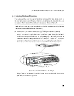
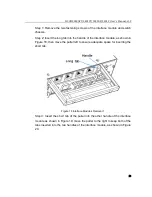
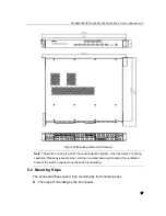
there is adequate space for it.
Step 2: As shown in Figure 26, move the switch in the direction of arrow 1 and
align the holes in the mounting brackets and the corresponding holes in the
rack; use 4 screws (M5×14) to fix the switch in the rack.
Figure 26 Mounting by Rear Panel
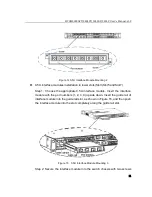
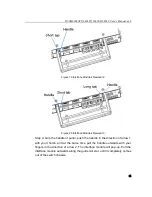
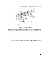
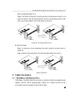
Removal steps
Step 1: U nscrew 4 sc rews fastening t he switch and t he r ack as shown i n
Figure 27.
Step 2: Remove the switch from the rack along the direction of arrow 1.
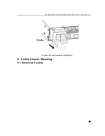
Figure 27 Removal
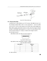
6 Cable Connection
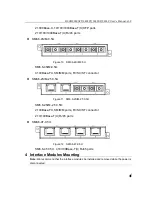
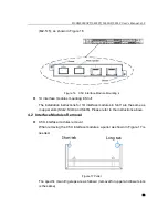
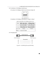
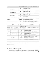
6.1 10/100Base-T(X) Ethernet Port
10/100Base-T(X) Ethernet RJ45 port can be connected to terminal equipment and
network devices with st raight-through c ables or cr ossover ca bles. R J45
connectors must be equipped at both ends of cable.


