


SICOM3028GPT/3424PT/3028GP/3424P User’s Manual-v1.2
18
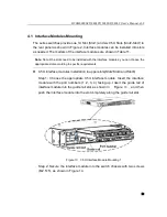
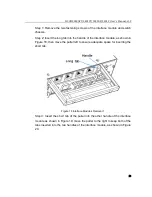
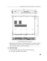
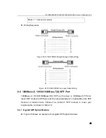
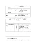
Step 1: Select the mounting position for the switch in the rack and ensure that
there is adequate space for it.
Step 2: As shown in Figure 24, move the switch in the direction of arrow 1 and
align the holes in the switch mounting brackets and the corresponding holes
in the rack; use 4 screws (M5×14) to fix the switch in the rack.
Figure 24 Mounting by Front Panel
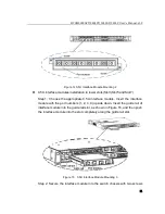
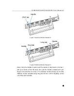
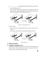
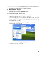
Removal steps
Step 1: U nscrew 4 sc rews fastening t he switch and t he r ack as shown i n
Figure 25.
Step 2: Remove the switch from the rack along the direction of arrow 1.
Figure 25 Removal
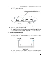
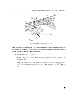
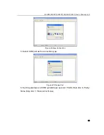
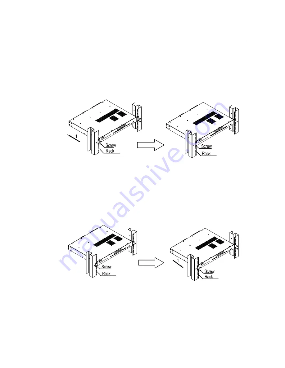
The steps of mounting by the rear panel
Step 1: Select the mounting position for the switch in the rack and ensure that


