


SICOM3028GPT/3424PT/3028GP/3424P User’s Manual-v1.2
13
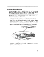
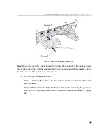
Step 1: Remove the two fastening screws of the interface module and switch
chassis.
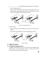
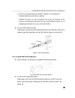
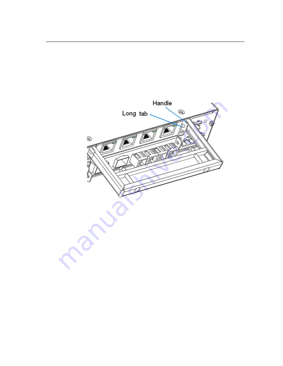
Step 2: Insert the long tab into the handle of the interface module, as shown in
Figure 18; then move the puller left to ensure adequate space for inserting the
short tab.
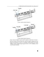
Figure 18 Interface Modules Removal 1
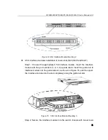
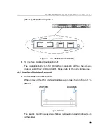
Step 3: Insert the short tab of the puller into the other handle of the interface
module as shown in Figure 19; move the puller to the right to keep both of the
tabs inserted into the two handles of the interface module, as shown in Figure
20.


