


SICOM3028GPT/3424PT/3028GP/3424P User’s Manual-v1.2
10
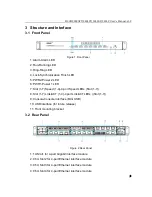
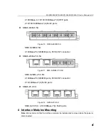
4.1 Interface Modules Mounting
The series switches provide one 1U Slot (Slot1) and six 0.5U Slots (Slot2-Slot7) in
the rear panel as shown in Figure 2. Interface modules can be installed into slots
as needed. The models of the interface modules are shown in Table 11.
Note:
Not all the slots need to be installed with the interface modules; you can choose the
appropriate slots according to specific requirements.
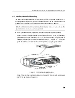
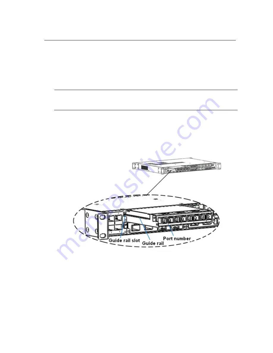
0.5U interface modules installation in upper slots(Slot2,Slot4 and Slot6)
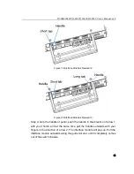
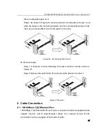
Step 1: C hoose the a ppropriate 0.5U interface m odule. Insert the interface
module with the port numbers (1, 2, 3, 4) facing up. Insert the guide rail of
interface module into the guide rail slot, as shown in Figure
13
, and t hen
push the interface module into the slot completely along the guide rail slot.
Figure 13 0.5U Interface Module Mounting 1
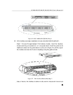
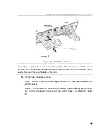
Step 2: Secure the interface module into the switch chassis with two screws
(M2.5×5), as shown in Figure 14.


