


SICOM3028GPT/3424PT/3028GP/3424P User’s Manual-v1.2
12
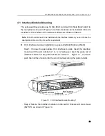
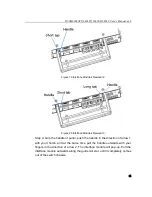
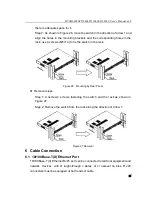
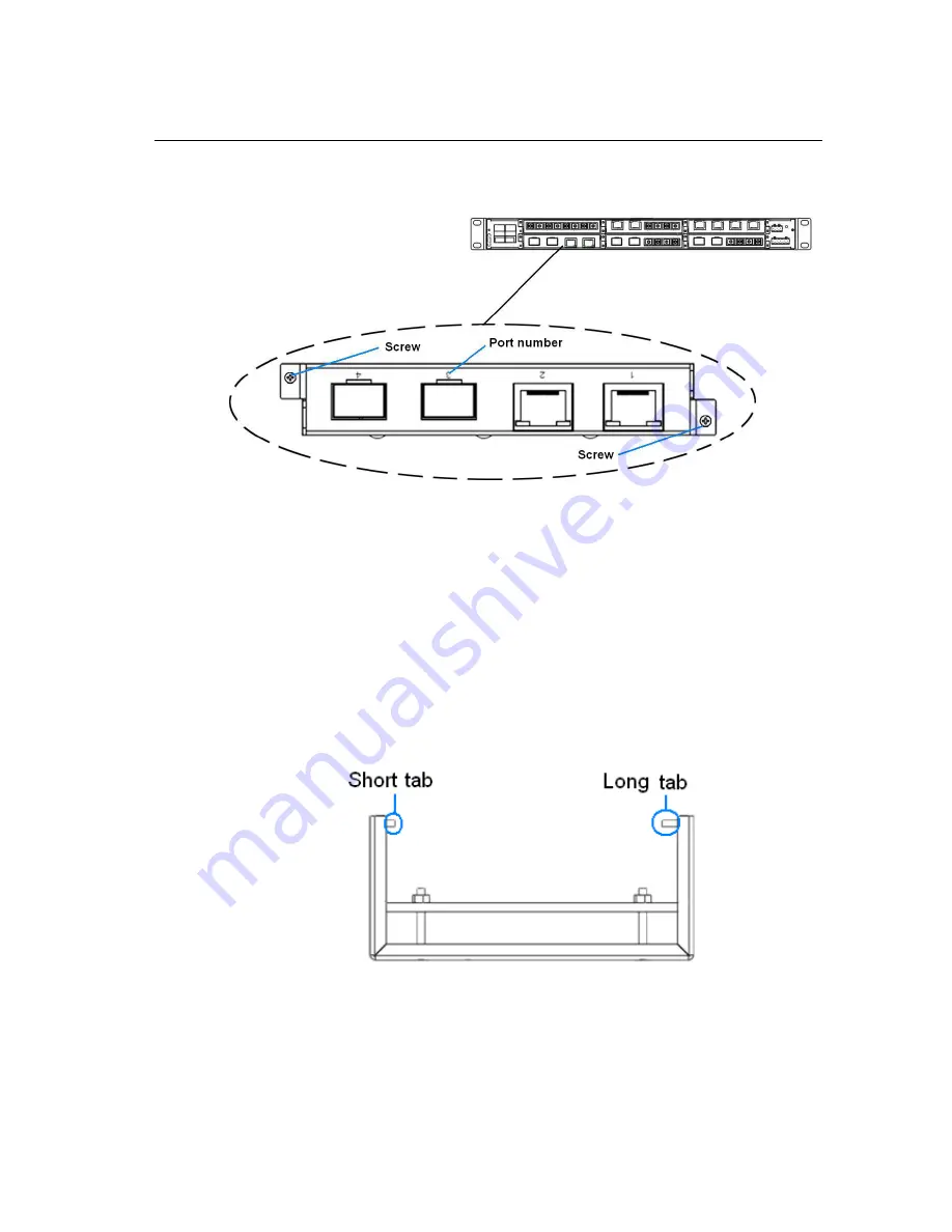
(M2.5×5), as shown in Figure 16 .
Figure 16 0.5U Interface Module Mounting 4
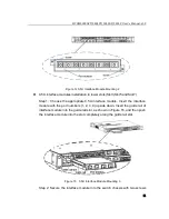
1U interface modules mounting in Slot1
The installation instructions for 1U interface modules in Slot1 are the same as
in upper slots (Slot2, Slot4 and Slot6). Please refer to the instructions above.
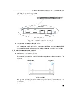
4.2 Interface Modules Removal
0.5U interface modules removal
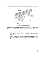
When removing the 0.5U interface modules, a puller as shown in Figure 17 is
needed.
Figure 17 Puller
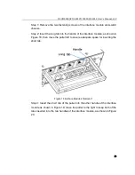
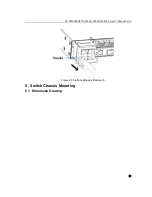
The specific mounting steps are as follows: (removal for upper and lower slots
is the same)


