


Diajekt Control CFC10
8
Status: 06/18/2014
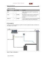
1.3.1 Mechanical Connections
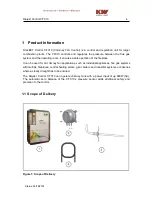
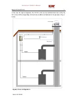
The CFC10 and the pressure sensor (DPT-A) are installed in the boiler room. In flue gas
systems with several fireplaces, the measuring probe (MP) should be installed between the
last fireplace and the chimney fan or as close as possible to the chimney fan inside the flue
gas pipe or the collecting pipe of the flue gas system. The measuring probe (MP) is
connected to the pressure sensor through the silicone tube and is placed below the
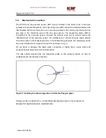
installation site of the pressure sensor. For installations in vertical flue gas pi pes, please
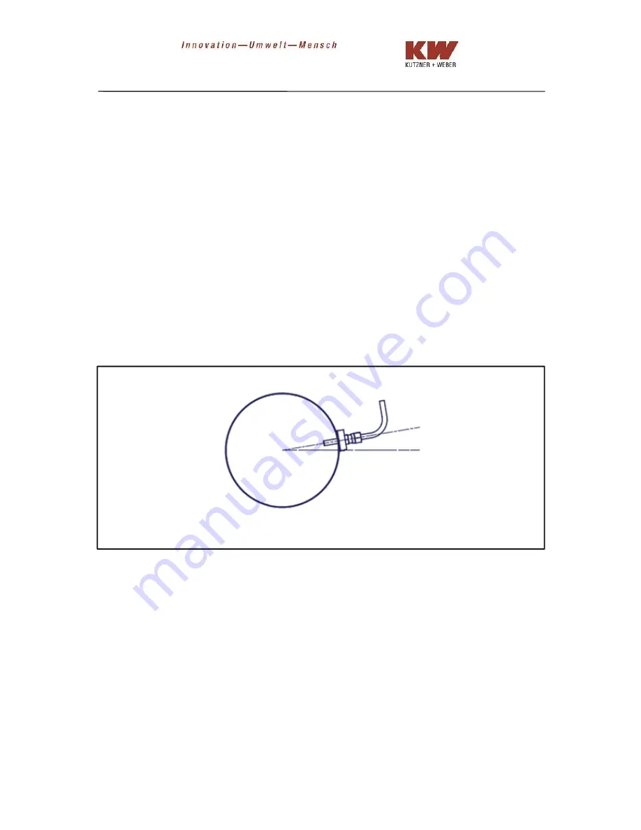
note the arrows on the measuring probe. In horizontal flue gas pipes, the measuring probe
has to be installed at an angle of at least 5% as shown in fig. 5.
Do not bend or damage the tubes when connecting or laying them. Leaky tubes and
connections will cause the control to malfunction.
The tube should ascend from the measuring probe to the pressure sensor so that no
condensate can accumulate in the tube.
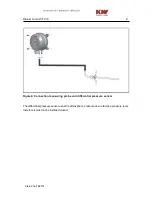
Figure 5: Installing the measuring probe in horizontal flue gas pipes
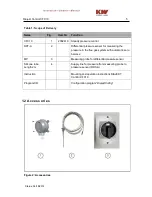
Please use the connection P2 (-) on the differential pressure sensor. This connection is
designed for negative pressure measurements.
Содержание CFC10
Страница 1: ...DIAJEKTControl CFC10 V2 0 Assembly Installation and Operation Instructions...
Страница 2: ......
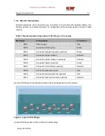
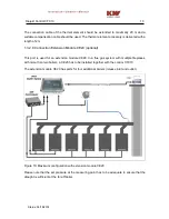
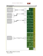
Страница 16: ...Diajekt Control CFC10 16 Status 06 18 2014 1 4 1 1 One Boiler Figure 11 Wiring scheme for one boiler...
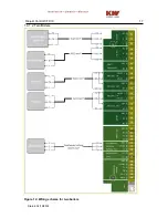
Страница 17: ...Diajekt Control CFC10 17 Status 06 18 2014 1 4 1 2 Two Boilers Figure 12 Wiring scheme for two boilers...