


Diajekt Control CFC10
14
Status: 06/18/2014
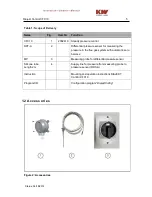
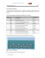
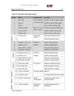
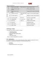
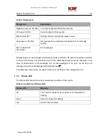
Table 4: Configuration of bushing clamps
Clamp
Name
Configuration
Function
1
Mains PE
230 VAC (50 Hz)
110 VAC (60 Hz)
Protective conductor mains supply
2
Mains N
Neutral conductor mains supply
3
Mains L
Outer conductor mains supply
4
Chimney fan PE
Max. 3A or up to
600W capacity
Protective conductor chimney fan
5
Chimney fan N
Neutral conductor chimney fan
6
Chimney fan L
Outer conductor chimney fan
O
pti
o
n
a
l
7
Chimney fan
Switch relay
(closer)
Switch relay COM connection
8
Switch relay NO connection
9
Release 1 input L (+)
24VDC or
230VDC
Input for release signal 1
10
Release 1 N (-)
Input for release signal 1
11
Relay COM connection
Output for release signal 1
12
Relay NO connection
Output for release signal 1
O
pti
o
n
a
l
13
Release 2 input L (+)
24VDC or
230VAC
Input for release signal 2
14
Release 2 N (-)
Input for release signal 2
15
Relay COM connection
Output for release signal 2
16 Relay NO connection
Output for release signal 2
O
pti
o
n
a
l
17
Alarm relay COM
Error report
Relay outlet COM connection
18
Alarm relay NO
Relay outlet NO connection
19
Alarm relay NC
Relay outlet NC connection
O
pti
o
n
a
l
20
Chimney fan GND
Set value display
Mass CF
21
Outlet CF power
CF analog outlet for set value display
O
pti
o
n
a
l
22
Input CF motor speed
Speed
measurement
Chimney fan analog input for
measuring speed
O
pti
o
n
a
l
23
Inlet CF feedback
Chimney fan
feedback
Digital feedback signal from
chimney fan
Содержание CFC10
Страница 1: ...DIAJEKTControl CFC10 V2 0 Assembly Installation and Operation Instructions...
Страница 2: ......
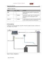
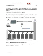
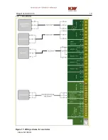
Страница 16: ...Diajekt Control CFC10 16 Status 06 18 2014 1 4 1 1 One Boiler Figure 11 Wiring scheme for one boiler...
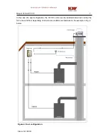
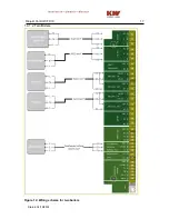
Страница 17: ...Diajekt Control CFC10 17 Status 06 18 2014 1 4 1 2 Two Boilers Figure 12 Wiring scheme for two boilers...