2-13
Installation
54-0144 Rev. C
Multiswitch Installation
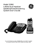
For multiple IRD/TV installations, an active multiswitch
(Channel Master model 6214IFD or equivalent) is placed
between the Antenna Unit and the IRDs. Figures 2-20 and 2-21
illustrate typical wiring arrangements for multiple IRD and
multiple multiswitches, respectively. Mount the multiswitch
unit in accordance with the manufacturer’s instruction sheet.
1. Connect the RF cable tagged “RF2” to the
multiswitch input labeled “LNB LHCP +18V”.
2. Connect a second RF cable to the multiswitch
input labeled “LNB RHCP +13V”.
3. Connect the multiswitch outputs to individual
IRD inputs. Use RG-6 or RG-11 cable terminated
with F-type connectors for all RF connections.
4. Terminate all unused output connectors with
75 ohm DC blocks (Channel Master #7184,
Radio Shack #15-1259 or equivalent).
Multiswitch
DC In
RHCP
+13v
VHF/UHF
LHCP
+18v
Out 1
Out 2
Out 3
Out 4
DC Power
IRD #1
IRD #2
IRD #4
IRD #3
TracVision Cruiser RF Connectors
RF1
RF2
TracVision Cruiser
Data Cable Connector
The data cable should be attached
to the master IRD. The master IRD
must remain powered for the
secondary IRDs to function
properly.
Figure 2-20
Connecting TracVision Cruiser to
Multiple IRDs
RG-6 or RG-11 (75 ohms) cable
or better is required for RF wiring.
Use of non-RG-6 or non-RG-11
(75 ohms) cables will result in
degraded performance and void
the warranty.