5-3
Maintenance
54-0144 Rev. C
5.4 Field Replaceable Unit
Procedures
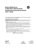
The following subsections provide detailed procedures for
repairing or swapping out field replaceable units. The
procedures refer to labeled items presented on the following
isometric diagrams, which are based on KVH assembly
drawings.
Figure 5-1
Antenna, PCB, and Rotating Plate
2
33
60
21
1
11
Figure 5-2
Close-up of Linear Actuator,
Pivot Bracket, and Pin