®
21
®
20
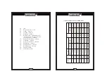
1.
L / C / R
2.
Q / D / R
3.
A(1KHz) / B(120Hz)
4.
P(PAL) / S(SER)
5.
A(AUTO) / M(MENU)
6.
0 / 1: Main Display MSD,
8: while changing range ,
9: OL
7.
6~10: Main Display Data
8.
9.
10.
LSD
11.
Main Display Range
12.
MSD
13.
12~15: Second Display Data
14.
15.
LSD
16.
Second Display Range , 9: OL
17.
Sequence 0~9 cycling
18.
MSD
19.
18~21: D value
20.
21.
LSD
22.
Range for D value , 9: OL
23.
MSD
24.
23~26: Q value
25.
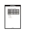
Ex.
[
±
1
9
9
9
9
]
Start
Code
Data
Format
Setting
Value
Stop
Code
[U±19999] :
REL SET setting value
[V±19999] :
Limits Hi setting value
[W±19999] :
Limits Lo setting value
[X±19999] :
TOL SET setting value
[Y±19999] :
TOL SET Hi setting value
[Z±19999]
:
TOL SET Lo setting value
After receiving of setting data from PC (U/V/W/X/Y/Z), and will send
out the receiving data again then it is convenient for PC to check the
accuracy of data output are total 7 digits.
c. Command [BXXXXXX]:
Exit the SETUP mode
(2) Read Data
Command N: Read Meter current data and status. Data format:
There are 39 ASCII code.
The Main Display data just send L/C/R data that don't process
before (like the data before REL). The Second Display data is the
same as Main.
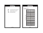
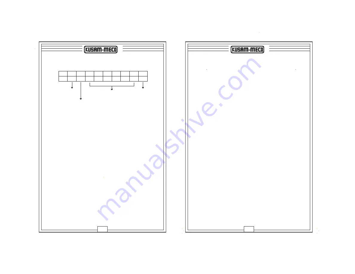
Bit.
0
1
2
3
4
5
6
7
8
U


