


• Start up the robot system in accordance with the chapter “Start-up and
recommissioning” in the operating instructions for the robot controller.
• Put the robot system into operation in accordance with the chapter
“Start-up and recommissioning” of the operating and programming in-
structions for the KUKA System Software (KSS).
7.3
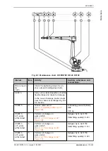
Starting up robots (machine frame mounting)
Description
The machine frame mounting assembly is used for installing robots on a
steel structure prepared by the customer, on a carriage of a linear unit, or
on an adapter plate.
8 hexagon bolts with conical spring washers are used for fastening the ro-
bot to a machine frame. A cylindrical pin and a flat-sided pin are provided
to ensure correct positioning.
This description is valid for the installation of floor, wall and ceiling-moun-
ted robots with the mounting variant “machine frame mounting”.
The robot must be rotated for wall and ceiling mounting. In doing so, it
must be secured such that an uncontrolled rotational motion or toppling is
impossible; the center of gravity must be taken into account
(
>>>
6.1 "Transporting the robot" Page 167
). When rotating the robot,
care must be taken not to damage the connectors, installation material
and/or energy supply system (optional). The wall-mounted or ceiling-moun-
ted installation is analogous to installation of the floor-mounted robot.
NOTICE
If a fixture is used, the manipulator must be secured in such a way that
slipping is impossible. Only approved fixtures with an adequate carrying
capacity may be used. Damage to property may otherwise result.
The installation and start-up of the robot controller, the tools mounted and
the applications are not described here.
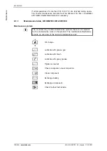
Equipment
The following equipment is required:
Designation
Article number
Lifting tackle/rope sling with sufficient
load-bearing capacity and suitable lifting
accessory
-
Fork lift truck or crane with adequate car-
rying capacity
-
LLA forklift slot KR IONTEC
0000-339-419
Set of Allen keys
1.5; 2; 2.5; 3; 4; 5; 6; 8; 10 mm
-
Torque wrench
min. 2 to 20 Nm
-
Torque wrench
min. 300 to 500 Nm
-
Material
The following material is required:
KR IONTEC
178/344 |
www.kuka.com
MA KR IONTEC V4 | Issued: 11.05.2021
Start-up
and
recommissioning
Содержание IONTEC KR 20 R3100
Страница 14: ...KR IONTEC 14 344 www kuka com MA KR IONTEC V4 Issued 11 05 2021 Introduction...
Страница 166: ...KR IONTEC 166 344 www kuka com MA KR IONTEC V4 Issued 11 05 2021 Planning...
Страница 188: ...KR IONTEC 188 344 www kuka com MA KR IONTEC V4 Issued 11 05 2021 Start up and recommissioning...
Страница 300: ...Fig 9 58 Wiring diagram axis A2_KS A1 A3 KR IONTEC 300 344 www kuka com MA KR IONTEC V4 Issued 11 05 2021 Repair...
Страница 301: ...Fig 9 59 Wiring diagram axis A3_KS A1 A3 KR IONTEC MA KR IONTEC V4 Issued 11 05 2021 www kuka com 301 344 Repair...
Страница 302: ...Fig 9 60 Wiring diagram axis A4_KS A1 A3 KR IONTEC 302 344 www kuka com MA KR IONTEC V4 Issued 11 05 2021 Repair...
Страница 303: ...Fig 9 61 Wiring diagram axis A5_KS A1 A3 KR IONTEC MA KR IONTEC V4 Issued 11 05 2021 www kuka com 303 344 Repair...
Страница 304: ...Fig 9 62 Wiring diagram axis A6_KS A1 A3 KR IONTEC 304 344 www kuka com MA KR IONTEC V4 Issued 11 05 2021 Repair...
Страница 310: ...KR IONTEC 310 344 www kuka com MA KR IONTEC V4 Issued 11 05 2021 Repair...
Страница 318: ...KR IONTEC 318 344 www kuka com MA KR IONTEC V4 Issued 11 05 2021 Decommissioning storage and disposal...
Страница 340: ...KR IONTEC 340 344 www kuka com MA KR IONTEC V4 Issued 11 05 2021 KUKA Service...