background image


KTR-STOP

®

 L light-xxx A-xx-xx 

Operating/Assembly instructions 

KTR-N 
Sheet: 
Edition: 

445123 EN 
1 of 21 


Please observe protection 

note ISO 16016. 

Drawn: 

2020-09-25 Shg/Wie 

Replacing: 

KTR-N dated 2019-11-21 

Verified: 

2020-11-05 Shg 

Replaced by: 


KTR-STOP

®

 L light-xxx A-xx-xx 


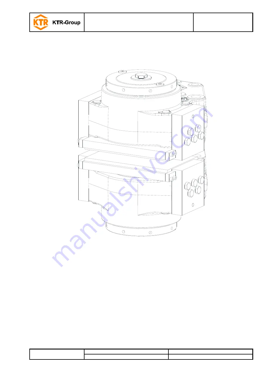
L light-xxx A-xx-xx is a spring-actuated brake in a fixed calliper design serving to 
generate a brake force onto a brake disk in order to decelerate a plant’s move-
ment or stop it, respectively, or keep it at standstill. 


Содержание KTR-STOP L light A Series

Страница 1: ...Drawn 2020 09 25 Shg Wie Replacing KTR N dated 2019 11 21 Verified 2020 11 05 Shg Replaced by KTR STOP L light xxx A xx xx L light xxx A xx xx is a spring actuated brake in a fixed calliper design se...

Страница 2: ...rage transport and packaging 5 3 1 Storage 5 3 2 Transport and packaging 5 4 Assembly 6 4 1 Components of the brake 6 4 2 Preparation of assembly 8 4 3 Brake pads 9 4 4 Assembly of the brake 9 4 5 Pre...

Страница 3: ...of brake disk mm 1000 Pressure connection G3 8 Oil bleed G1 4 Operating temperature C 20 to 50 1 The friction coefficient each depends on the application please consult with KTR Table 2 Clamping forc...

Страница 4: ...y instructions The operating assembly instructions are part of your product Please store them carefully The copyright for these operating assembly instructions remains with KTR STOP Warning of persona...

Страница 5: ...the technical data see chapter 1 Unauthorized modifications on the brake design are not admissible We will not assume liability for any damage that may arise In the interest of further development we...

Страница 6: ...The brake is supplied in pre assembled condition Before assembly the brake has to be inspected for completen ess Components component assemblies of brake Type L light xxx A xx xx Compo nent subas semb...

Страница 7: ...iston 1 8 1 Pressure cylinder 1 9 1 Pipe 1 10 1 Cap screw DIN EN ISO 4762 1 11 1 Centering sleeve 1 12 1 Set of disk springs 1 13 1 Centering pin 1 14 1 O ring 1 15 1 Sealing plug 1 16 1 O ring 1 17 1...

Страница 8: ...sp the stand for the brake as well as the brake disk must be inspected for dimensional accuracy For that purpose inspect the connection dimensions connection surfaces and tolerances as spe cified in t...

Страница 9: ...ssure without transport lock for reasons of space please consult with KTR STOP In order to avoid any injuries please always make use of proper lifting equipment In the pad retainers there are M12 thre...

Страница 10: ...ively Push the connection screw screwed in before through the second half of the brake and align it symmetrically Fasten the connection screw at the tightening torques spe cified in table 3 Repeat thi...

Страница 11: ...with the full braking power on one side in case if one half of the brake fails It is not recommended to use steel plugs for venting Connect the leakage oil line to the brake see illustration 9 and 10...

Страница 12: ...kets may be damaged and the operation of the brake is no longer ensured Illustration 11 Pressure connection of several brakes in parallel Illustration 12 Pressure connection of several brakes in a ser...

Страница 13: ...ort while to make sure that the brake is flushed with hydraulic oil Repeat this process until a stream of clean oil dissipates from the miniature measuring hose Remove the miniature measuring hose If...

Страница 14: ...oth sides Illustration 13 Setting re setting of the brake Tilting of the safety plate can be untightened by rotating the centering pin component 1 13 by 2 3 Measure the gap between the brake disk and...

Страница 15: ...not exceed 500 mm2 s and the viscosity during operation should not fall below 12 mm2 s Filtration When filling and re filling the hydraulic system and replacing the hydraulic liquid the oil needs to...

Страница 16: ...ly untightened against a stop Release the pressure fully from the hydraulic system Make sure that the entire brake system is depressurized STOP Parts released or falling down may cause injury to perso...

Страница 17: ...ling down may cause injury to persons or damage on the machine Secure the components before disassembly Never keep your fingers between brake disk and brake when applying the brake in order to prevent...

Страница 18: ...tool to ensure the same arrangement of disk springs washer and adjustment washer s with re assembly of the brake Press the brake piston component 1 7 with the centering sleeve component 1 11 the cent...

Страница 19: ...ponent 1 13 and the pressure cylinder component 1 8 into the housing and press it against a stop A mounting device may be necessary for that purpose please consult with KTR Push the set of disk spring...

Страница 20: ...put special emphasis on leakages corrosion wear of brake pads and the condition of the screw connections If you realize any irregularities please perform repairs accordingly Operation of sensor There...

Страница 21: ...f the state wear sensor is wired properly This provides a signal since a switch NO is locked which is normally unlocked In case of damages like for example faulty cables bad connections etc the signal...

Отзывы: