WK
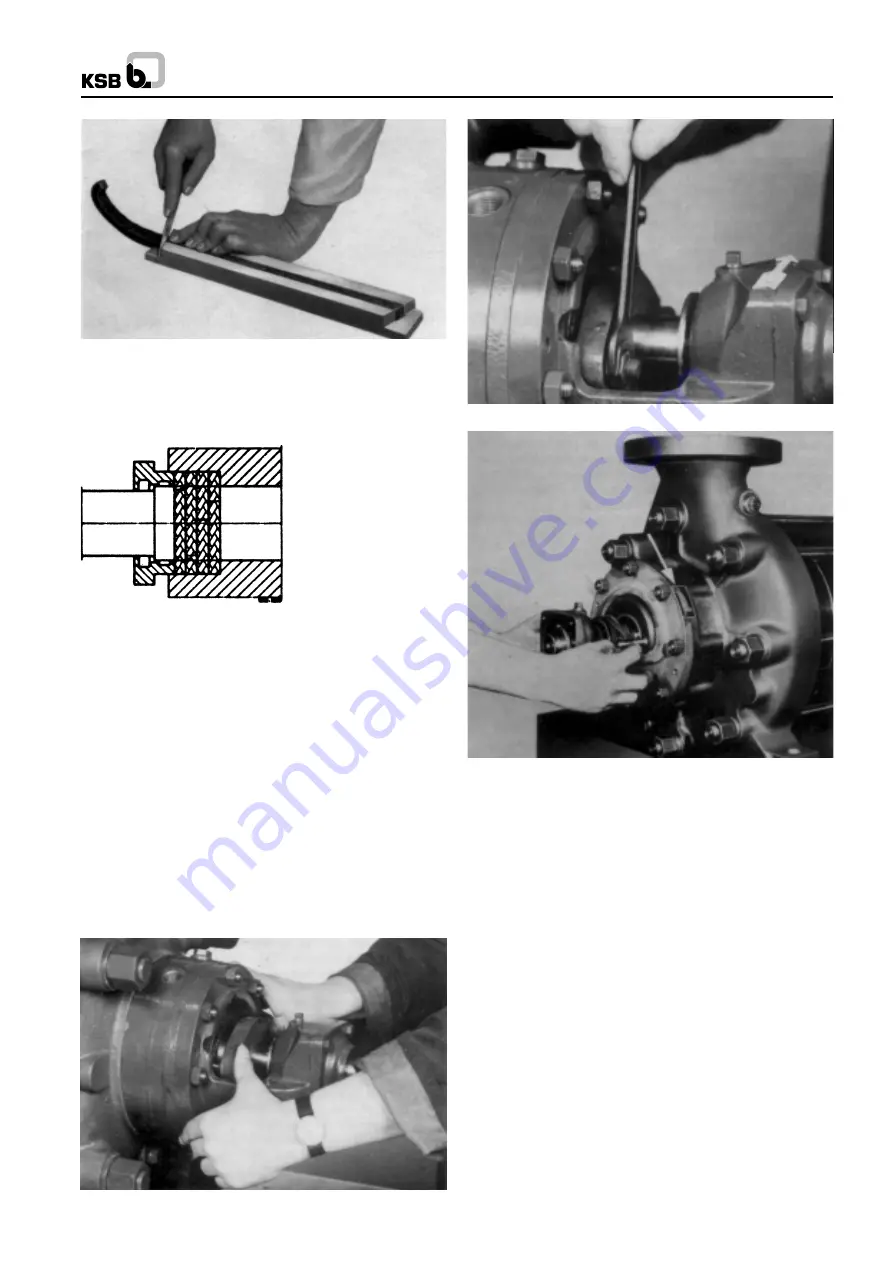
Fig. 20 Cutting the packing rings of length.
To cut the packing rings to correct length, use a suitable wooden
cutting jig (we can supply same on request), to ensure that the
packing rings are of the correct length and that their ring butts
come into correct contact with one another (see Fig. 20).
If the packing rings are either too long or too short, the stuffing
box will not be able to perform its function properly. In the case
of asbestos-graphite packing material, the rubbing faces of
the individual rings should be lightly coated with molybdenum
disulphide before insertion in the packing compartment. The
first packing ring is then inserted and pushed home into the
compartment with the aid of the stuffing box gland.
The following packing rings are then inserted into the packing
compartment one by one, making sure that the butt joint of
each ring is offset 90
0
approx. in relation to the butt joint of the
preceding ring; the individual rings are pushed home into the
packing compartment with the aid of the stuffing box gland
(see Fig. 21 and 22). The packing rings should only be pressed
lightly against one another. They should not be inserted in the
packing compartment in such a way that a clear gap of 6 to 8
mm is left at the outer end of the compartment for the positive
guidance of the stuffing box gland.
Fig. 22 Insertion of packing rings with the aid of the stuffing
box gland
Fig. 23 Tightening the stuffing box gland
The inserted packing rings should then be compressed
moderately with the aid of the stuffing box gland (452) and the
nuts (see Fig. 23). Then the nuts should be slackened again
by one to two complete turns, and thereafter tightened lightly
by hand. The correct and even seating of the stuffing box gland
(452) should be checked when the pump is subjected to suction
pressure, by inserting a feeler gauge between the gland (452)
and the shaft protection sleeve (524.1/.2).
In the case of the special stuffing boxes, a seal cage ring is
also inserted in the packing compartment, viz. at the centre of
the compartment (between the packing rings) in the case of
construction ‘‘VSM’’, and at the bottom of the compartment in
the case of construction ‘‘VSH’’. In these cases, an information
plate (see Fig. 20) is affixed to the stuffing box housing, showing
the position of the lantern ring. The seal cage ring must register
beneath the drilled hole in the stuffing box housing, to enable
the sealing of flushing liquid to flow through the hole and the
ring. The sealing or flushing liquid pressure should be 1 to 4
bar above the pressure reigning in the packing compartment
of the stuffing box.
The packing of the stuffing boxes should be carried out with
great care, to avoid an excessively high radial pressing force
of the packing rings against the shaft protection sleeve, which
might damage the latter. If the shaft protection sleeve is scored
or grooved, even a new packing cannot be expected to last
very long in service.
Fig. 24 Information plate regading seal cage ring
Fig. 21 Stuffing box packing
6
Содержание WK 100
Страница 34: ...WK NOTES ...
Страница 35: ...WK NOTES ...
Страница 36: ...WK NOTES ...
Страница 37: ...WK ...


