WK
12
Lever
13
Taper grooved dowel pin
14
Bottom spider
15
Top spider
16
Cylindrical helical spring
17
Socket head cap screws
18
Socket head cap
19
Taper grooved dowel pin
20
O-ring
21*)
O-ring
22
Valve
23
Cylindrical helical spring
24
Manual operation nozzle
25
Multistage throttle
*) Not applicable for temperature above 130
0
C and valve
pressure rating above PN 100 (Metal to metal sealing provided).
Parts 8-13 (Complete leak-off nozzle) can be replaced
individually.
9.4
Final Coupling Check
After completion of the piping assembly, the coupling alignment
should be checked once more (See Section 8.3 ‘‘Aligning the
Coupling’’). It must be possible to rotate the pump rotor without
effort by hand at the coupling, when the stuffing boxes are not
packed. If the alignment is satisfactory (no misalignment having
taken place), the driver can be dowelled with cylindrical dowel
pins.
9.5
Measuring Instruments
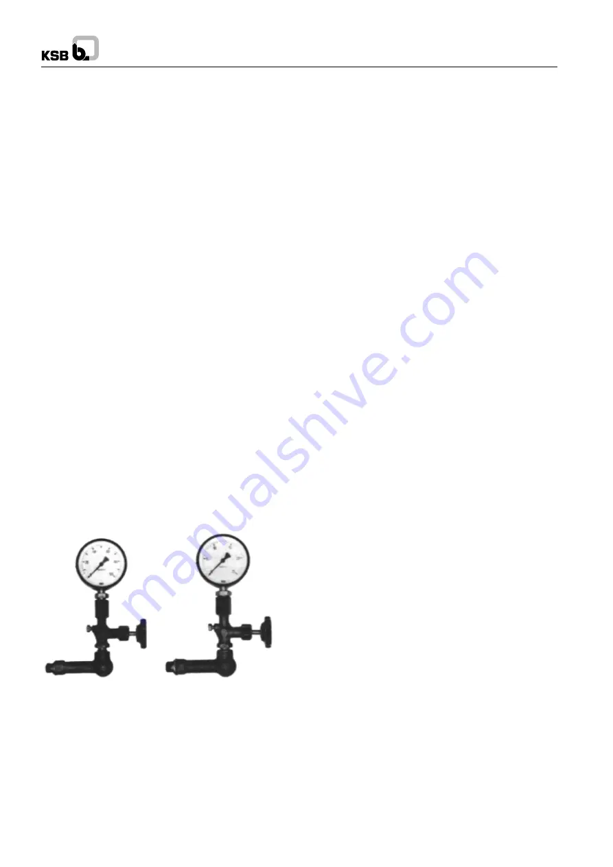
Each pump should be equipped with two pressure gauges,
one at suction nozzle and the other at the discharge nozzle;
their measuring range should be suitable for the prevalent
pressure conditions, and they should be provided with a stop
cock or stop valve. If the suction conditions demand it (e.g.
suction lift operation), the gauge on the suction nozzle should
be pressure vacuum gauge (measuring instruments can be
supplied by us on request see Fig. 50).
10. Commissioning
10.1 Preliminary Remarks regarding Commissioning
If the initial start up does not take place immediately after the
erection of the pumping set, but only weeks or even months
later, it will be necessary to carry out the following checks once
again before start up :
1.
Renewed direction of rotation check of driver with pump
disconnected from the driver.
Even a relatively short start up run in reverse rotation may
result in damage to the pump. The overspeed trip check
of the turbine or turbine driven pumps should also be
carried out with the turbine disconnected from the pump.
2.
Check correct coupling alignment again.
3.
Dismantle pump bearings, clean them and reassemble
them (as described in section 11, ‘‘Dismantling the
Pump’’).
4.
Fill-in oil, or check grease fill respectively.
5.
Pack the stuffing boxes (see section 1.5.1 ‘‘Stuffing
Boxes’’).
10.2 Start-up
1.
Check oil level in pump bearings, if necessary top up the
oil fill until oil starts pouring out of the over flow hole.
2.
Check condition of stuffing boxes (451.1 / 451/2). The
stuffing box gland should penetrate deep enough in the
stuffing box to ensure positive guidance, and must not be
tightened askew (see section 1.5.1 ‘‘Stuffing Boxes’’).
3.
In the case of a mechanical seal with internal circulation,
open flow controller fully (only applies to the initial start-
up).
4.
Turn on cooling liquid supply and check that it flows away
freely.
5.
Open suction valve fully.
6.
Leave isolating valve in discharge line closed for the time
being.
7.
The pump must be completely primed with the product
pumped. Before it is started up for the first time, the pump
should be vented through the connection on the discharge
pressure gauge, or through the vent valves, if provided.
The discharge line should also be vented through valves
situated at the apex of the line.
8.
Open the shut off valve on the minimum flow line of the
automatic recirculation valve and lock it open, to prevent
unintentional closure. If the automatic recirculation valve
is equipped with a manual operation line, open the valve
in this line.
If the pump is only equipped with a manually controlled
minimum flow (by pass) line, open the isolating valve in
this line.
If a check valve or non return valve is incorporated and if
the pump is to be started up against an open discharge
valve, make sure that the non return valve is closed as a
result of the back pressure (e.g. the boiler pressure). If
the full back pressure does not reign at the time of start
up the pump should only be started up against a closed
discharge valve.
9.
Check suction pressure and temperature. Check whether
the saturation condition of the fluid pumped reigns inside
the pump with the aid of the saturation curve. No vapour
formation must be allowed to take place inside the pump.
10. When starting up for the first time, and also after a
prolonged plant shutdown, start up the driver with the
pump coupled to it, then switch off the driver again
immediagely. Check that the rotor runs down to a standstill
Fig. 50 Arrangement of measuring instruments
13
Содержание WK 100
Страница 34: ...WK NOTES ...
Страница 35: ...WK NOTES ...
Страница 36: ...WK NOTES ...
Страница 37: ...WK ...


