WK
smoothly and lightly, and check that the pump bearings
are being supplied with oil. The pump rotor must not stop
with a sudden jerk.
11. In the case of a turbine driven pump, run the pump up to
full sped rapidly.
12. Watch the discharge pressure, to make such the pump
attains the prescribed discharge pressure.
13. If applicable, close the manually operated minimum flow
line when the operating rotational speed has been
attained. Check whether minimum flow line becomes
warm.
14. Adjust rate of flow of cooling liquid for the mechanical
seal by means of the flow controller. The temperature at
the mechanical seals should not exceed 70
0
C.
15. Open isolating valve in the discharge line.
Caution :
If the pump is commissioned on hot fluid, the casing
will heat up more rapidly than the connection rods (905)
because of its direct contact with the fluid pumped. The casing
will become longer as a result of thermal expansion. The pre-
stressing of the connection rods will increase and the surface
pressure (contact pressure) on the flat gaskets will attain a
maximum value. Under such stress conditions, the gaskets
which are still new will bed themselves down. When the pump
has warmed up all over, the connection rods (905) may suffer
such a reduction in prestressing that the pump may start leaking
at the stage casings, especially in the case of pumps with a
large number of stages. In order to avoid such leakage, the
connection rods (905) should be tightened up after the first
few ‘‘hot’’ starts on a new or reconditioned pump.
10.3 Operation and Supervision of Pump
1.
Pumps operating at constant speed may usually be
operated at the point of optimum efficiency, at total heads
up to 90% of design head providing that suction head
and the motor horsepower are adequate.
2.
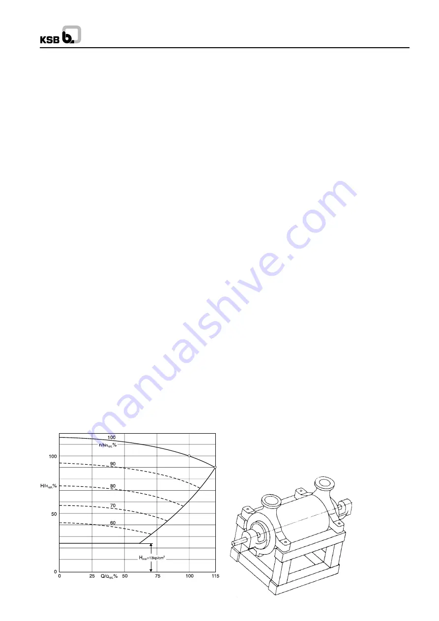
Pumps operating at constant speed may usually be
operated within the range indicated in the pump operating
diagram below. It should be noted that the throughout
which can be achieved decreases with decreasing speed
and pressure (see Fig. 51).
3.
When filling the boiler, the operating limits specified in 1
and 2 above should not be exceeded i.e. the discharge
valve should be partially closed to ensure that the pressure
does not fall below the minimum discharge pressure
corresponding to the particular speed or capacity at which
the pump is operated at the time. If the rate of flow drops
below the minimum flow, the minimum flow device starts
operating. Any prolonged operation within the response
range of the minimum flow device should be avoided as
far as possible, because this will cause premature wear
on the control and throttling organs.
10.4 Shutting the pump down
1.
Close isolating valve (gate valve or globe valve) in the
discharge line. If applicable, check the opening point of
the minimum flow device from time to time.
2.
Switch off driver and watch the pump run down smoothly
to a standstill. The pump rotor should not stop with a
sudden jerk.
3.
If applicable, turn off the sealing, circulation or flushing
liquid.
4.
The cooling liquid supply can be partially throttled, but it
should only be turned off completely when the temperature
inside the pump measured at the pump nozzle, has
dropped below 80
0
C. The suction valve should remain
open unless the pump is being taken out of service of a
prolonged period and it being drained.
10.5 Preserving the Pump
If the pump is taken out of service for a prolonged period, it is
advisable to dismantle it completely. Proceed as described in
section 11 ‘‘Dismantling’’. All components should be thoroughly
cleaned, dried and all bright parts coated with grease.
Thereafter the pump should be reassembled. All apertures on
the pump should be plugged with wooden stoppers soaked in
oil or blanked off with wooden cover plates fitted with O-rings.
A sachet filled with silicagel (silicagel absorbs moisture) should
be attached to the inside faces of the oil soaked wooden cover
plates on the suction and discharge nozzles (i.e. inside the
nozzles).
The packing should be removed from the stuffing box
compartments and these should be sealed by oil-soaked
wooden half tubes, each provided with two O-rings, in order to
prevent the penetration of moisture (not applicable to pumps
fitted with mechanical seals).
Caution :
Only use acid free oils and greases when preserving
the pump.
Fig. 51 Pump operating diagram
Fig. 52 Transport frame, Pump feet at shaft centreline heigh
14
Содержание WK 100
Страница 34: ...WK NOTES ...
Страница 35: ...WK NOTES ...
Страница 36: ...WK NOTES ...
Страница 37: ...WK ...


