background image


KRONE ISOBUS-Terminal CCI 100


95 


Pos: 61.46.15 /BA/Info-Center/CCI-ISOBUS-Terminal/CCI-EasyCut/EasyCut B 1000/Hauptmenüs/Hauptmenüs alte Ausführung/Hauptmenü 1 Einstellungen/Menü 1-2 Breitenverschiebung einstellen @ 93\mod_1327506050083_78.docx @ 790805 @ 3 @ 1 


11.2.2 

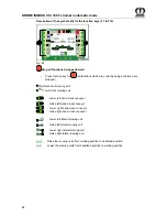
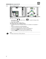
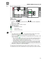
Menu 1-2 'Setting lateral displacement'   

1-2

CC000519

Auto

Fig. 54 
Main menu 1 'Settings' appears. 

• 

Press function key 

 or 

 to select menu 1-2 (

Auto

). The symbol is displayed with a 

grey background. 

• 

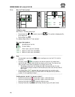
Press function key 


The display shows menu 1-2 'Setting lateral displacement'. 
 
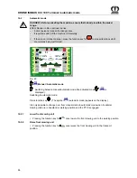
The lateral displacement function allows both lateral mowing units to be shifted to the right or 
left at the same time (for mowing in one direction, then the other), so that when mowing on a 
slope no crop sections remain standing. The upper values (A) can be adopted automatically 
diagonally for the lower values (B). 
 
• 

Select the selection box (A) using the scroll wheel. The selection box is highlighted in 
colour.  

• 

Press the scroll wheel (a new input field appears).  

• 

Turning the scroll wheel increases or reduces the value. 

• 

Press the scroll wheel to apply the setting and exit the selection box. 

• 

Press function key 


to close the currently displayed menu. 

• Pressing 

the 

 key for a little longer calls up the basic screen. 


Pos: 61.46.16 /BA/Info-Center/CCI-ISOBUS-Terminal/CCI-Rundballenpressen/Grundbild/Hinweis Einstellung über Touchscreen @ 79\mod_1315290154790_78.docx @ 701913 @  @ 1 


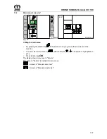
Note 

The values can also be set via the touchscreen. 


Pos: 61.46.17 /Layout Module /---------------Seitenumbruch---------------- @ 0\mod_1196175311226_0.docx @ 4165 @  @ 1 

Содержание EasyCut B 1000 CR

Страница 1: ...Original operating instructions Disc Mower EasyCut B 1000 CV EasyCut B 1000 CV Collect EasyCut B 1000 CR EasyCut B 1000 CR Collect from serial no 888 906 Order no 150 000 161 03 en 18 11 2014 ...

Страница 2: ...Machinery and EC Directive 2004 108 EC EMC The signing Managing Director is authorised to compile the technical documents Spelle 07 01 2014 Dr Ing Josef Horstmann Managing Director Design and Development Year of manufacture Machine No Pos 2 BA Vorwort Sehr geehrter Kunde 0 mod_1195626300326_78 docx 905 1 Dear customer Dear customer You have now received the operating instructions for the KRONE pro...

Страница 3: ...1 Identification Plate 18 4 2 Information Required for Questions and Orders 18 4 2 1 Contact 18 4 3 Introduction 19 4 3 1 Re Ordering the Adhesive Safety and Information Labels 19 4 3 2 Affixing the Adhesive Safety and Information Labels 19 4 4 Position of the Adhesive Safety Stickers on the Machine 20 4 5 Position of the Adhesive Safety Stickers on the Machine 22 5 Technical Data of the Machine 2...

Страница 4: ...ff when the machine is not connected 54 8 2 7 Switching the terminal on off when the machine is connected 55 8 2 7 1 Start screen 55 9 KRONE ISOBUS CCI 100 Terminal manual mode 56 9 1 Display Areas on the Screen 56 9 1 1 Status line area I 57 9 1 2 Displays in the main window II 58 9 2 Raise Lower front mowing unit basic dialogue 64 9 2 1 Lower front mowing unit 64 9 2 2 Raise front mowing unit 64...

Страница 5: ...ross conveyor 87 10 2 5 Speed Control of Cross Conveyor Belts 87 10 2 6 Raise Lower lateral mowing units 87 10 2 7 Lowering All Mowing Units from Headland Position to Working Position 88 10 2 8 Raising All Mowing Units from Working Position to Headland Position 88 10 2 9 Increasing Decreasing the overcut 89 10 2 10 Increasing Decreasing the lateral displacement 89 11 KRONE ISOBUS Terminal CCI 100 ...

Страница 6: ...owing 144 14 2 1 Folding down the Safety Device 145 14 2 2 Adjusting the lateral suspension arm 146 14 3 From transport into working position 147 14 3 1 Lowering the lateral mowing units from transport to headland position 147 14 3 1 1 Protection for wild animals 148 14 3 2 Lowering All Mowing Units from Headland Position to Working Position 148 14 4 Headland Position 149 14 4 1 Raising All Mowing...

Страница 7: ...r Drive Gearbox 184 18 3 Angular gearbox 185 18 3 1 Top part 185 18 4 Angular gearbox 186 18 4 1 Bottom part 186 18 5 Gearbox for Top Roller Drive 187 18 6 Oil level check and oil change on the cutter bar 188 18 6 1 Oil change 188 18 6 2 Checking the oil level 188 19 Maintenance Blade Changing 189 19 1 Checking the Cutter Blades and Blade Holder 189 19 1 1 Cutter Blades 190 19 1 2 Blade screw conn...

Страница 8: ... conveyor 215 22 5 3 Raise Lower both cross conveyors simultaneously 215 Speed control of transport belts 215 22 5 4 Speed Control of Cross Conveyor Belts 215 22 6 Bar on cross conveyor is bent 216 22 7 Hydraulic system 216 22 7 1 Filling Quantities and Lubricant Designations 217 22 7 2 Oil Tank 217 22 7 3 Checking the oil level 218 22 7 4 Oil change 218 22 7 5 Replacing the hydraulic oil filter 2...

Страница 9: ..._1204546850246_78 docx 70549 1 Note In the operating instructions which follow the disc mower will also be referred to as the machine Pos 6 4 BA Vorwort Beachten Sie für Maschine 0 mod_1195626904076_78 docx 944 1 Please note The operating instructions are part of your machine Only operate this machine after you have been trained to do so and according to these instructions It is essential to obser...

Страница 10: ...etriebsanleitung Einführungstext 2012 07 27 09 59 06 0 mod_1195637804826_78 docx 1098 2 1 2 2 Identifying Symbols in the Operating Instructions The safety instructions contained in this manual which could result in personal injury if not followed are identified by the general danger sign Pos 13 BA Sicherheit 6 Überarbeitete Warnhinweise Kennzeichnung der Gefahrenhinweise 2012 07 26 15 10 30 28 mod...

Страница 11: ...responsibility and monitoring of personnel Should personnel lack the required knowledge they must receive the required training and instruction The operator must ensure that the contents of these operating instructions have been fully understood by personnel Repair work not described in these operating instructions should only be performed by authorised service centres Pos 20 2 BA Sicherheit Gefah...

Страница 12: ...Use extreme caution when attaching or detaching implements onto or from the tractor 12 Always attach ballast weights properly to the fixing points provided 13 Observe permitted axle loads gross weight and transport dimensions 14 Check and attach transport equipment such as lighting warning devices and protective equipment 15 Actuating mechanisms cables chains linkages etc for remote controlled dev...

Страница 13: ...attaching or detaching implements onto or from the tractor 2 Couple the respective application devices to the appropriate couplings e g three point suspension only and secure them in a way transport use that excludes inadvertent lifting or lowering of the device 3 When using three point linkage the attachment categories of the tractor and the device e g PTO speed hydraulic system must be coordinat...

Страница 14: ...t make sure that no person is in the danger zone of the device 10 Never switch on the PTO if the engine is switched off 11 No one should be in the vicinity of the rotating PTO or PTO shaft when the PTO is in use 12 Always switch off the PTO shaft when the angle is too large or the PTO shaft is not required 13 Caution After disengaging the PTO danger due to the flywheel running on Keep away from th...

Страница 15: ...ed the function will be reversed e g raising lowering Risk of accident 5 When searching for leaks use suitable aids to avoid the risk of injury 6 Liquids escaping under high pressure hydraulic oil can penetrate the skin and cause serious injury Seek medical help immediately should injuries occur Danger of infection 7 Before working on the hydraulic system depressurise the system and switch off the...

Страница 16: ...cing working tools with cutting edges use suitable tools and gloves 5 Oils greases and filters must be disposed of correctly 6 Always disconnect the power supply before working on the electrical system 7 If protective devices and guards are subject to wear check them regularly and replace them in good time 8 When performing electrical welding work on the vehicle and mounted devices turn the power ...

Страница 17: ... of the operating instructions The limit values listed in the data charts should not be exceeded under any circumstances Pos 21 BA Sicherheit Arbeiten im Bereich von Hochspannungsleitungen 11 mod_1223357468516_78 docx 145505 2 1 3 10 Working in the vicinity of power transmission lines 1 Always take great care when working under or in the vicinity of power transmission lines 2 Ensure that when in o...

Страница 18: ...g the machine or ordering spare parts be sure to provide type designation machine number and the year of manufacture of the relevant machine To ensure that these data are always available we recommend that you enter them in the fields above Note Authentic KRONE spare parts and accessories authorised by the manufacturer help to ensure safety The use of spare parts accessories or additional equipmen...

Страница 19: ...legible adhesive labels Following repair work always attach appropriate adhesive safety stickers to all the replaced modified or repaired components Never clean areas carrying an adhesive safety label using a high pressure cleaner Familiarise yourself with the statement of the warning pictograms The adjacent text and the selected location on the machine provide information on the special danger sp...

Страница 20: ...95634967326_78 docx 1020 2 1 4 4 Position of the Adhesive Safety Stickers on the Machine Pos 37 BA Sicherheit Aufkleber EasyCutSicherheitsaufkleber EasyCut B 1000 CV CR 2014 10 16 16 06 20 211 mod_1389606340961_78 docx 1736368 1 ECB00060_1 3 3 2 2 3 3 1 2 2 4 4 4 4 5 CR 3 CR 3 Fig 2 EasyCut B 1000 CV EasyCut B 1000 CR ...

Страница 21: ...pletely Do not touch any moving parts of the machine Wait until they have come to a complete stop b Move the safety devices into protective position prior to start up c When the machine is running keep your distance Order no 939 576 0 4x 939 410 2 STOP 939 572 0 942 197 1 a b c 3 While parts are moving never reach into areas where there is a risk of being crushed Order no 942 196 1 4x for CV desig...

Страница 22: ...Position of the Adhesive Safety Stickers on the Machine Pos 41 BA Sicherheit Aufkleber EasyCutSicherheitsaufkleber EasyCut B 1000 CV Collect EasyCut B 1000 CR Collect 2014 10 17 07 07 53 211 mod_1389608771812_78 docx 1737010 1 ECB00043_2 3 3 2 4 5 5 4 2 3 3 1 2 2 6 6 6 6 4 3 3 3 7 8 8 CR 3 CR 3 Fig 3 EasyCut B 1000 CV Collect EasyCut B 1000 CR Collect ...

Страница 23: ... start up c When the machine is running keep your distance Order no 939 576 0 4x 939 410 2 STOP 939 572 0 942 197 1 a b c 3 While parts are moving never reach into areas where there is a risk of being crushed Order no 942 196 1 8x in case of CV design 10x in case of CR design 942 196 1 4 Danger due to rapidly circulating conveyor belt Order no 942 200 1 4x 5 939 472 2 Danger in the swivel range of...

Страница 24: ...Transport height mm 4 000 Number of mowing discs 12 Number of mowing drums 4 Conditioner system V shaped steel tines Speed of the conditioner rpm 600 900 Width of conditioner system rpm Cross conveyors Standard Acreage ha h 10 14 Power consumption kW HP 130 180 145 200 PTO speed rpm 1000 Hydraulic connections required 1 x EW and free reverse Load sensing capability Standard Service weight kg appro...

Страница 25: ...eight mm 4200 Transport height mm 4000 Number of mowing discs 12 Number of mower drums 4 Conditioner system Roller conditioner Cross conveyor belts Series Acreage output ha h 10 14 Power requirement kW HP 130 180 145 200 PTO speed rpm 1000 Required hydraulic connections 1 x single action and free return LoadSensing capable Series Dead weight kg approx 3420 approx 3900 SA single action control unit...

Страница 26: ...t 32 mod_1253100514124_78 docx 311746 1 ENVIRONMENT Disposal and storage of lubricants Effect Environmental damage Store lubricants in eligible containers according to statutory provisions Dispose used lubricants according to statutory provisions Pos 53 BA Wartung Tabellen_Füllmengen Mähwerke Technische Daten Betriebsstoffe Füllmengen EC B 1000 101 mod_1330599083129_78 docx 896949 1 Filling quanti...

Страница 27: ...Machine 27 Pos 55 Layout Module Diese Seite ist bewusst freigelassen worden 1 mod_1201783680373_78 docx 54443 1 This page has been left blank deliberately Pos 56 Layout Module Seitenumbruch 0 mod_1196175311226_0 docx 4165 1 ...

Страница 28: ...possibility of rolling back Wait until all machine parts have come to a complete stop They must also been cooled completely Pos 57 6 BA Sicherheit 7 Gefahrenhinweise alt Gefahr Fehlerhafter Zusammenbau 1 mod_1202224212591_78 docx 58171 1 Danger Incorrect assembly Effect Danger to life serious injuries or serious damage to the machine Only authorised service centres may assemble the machine The mac...

Страница 29: ...he hydraulic system to the tractor Check the density of the hydraulic system Check whether the tractor meets the requirements of the machine Check axle loads minimum ballast and total weight Adapt the coupling points to the tractor is necessary Check universal shaft length and adapt the length if necessary In transport position the cross conveyor must be checked for firm attachment Check the conve...

Страница 30: ...ensor Test Note Turn the PTO shaft around once manually Observe the display when turning The status of the sensor changes from alive to not alive and vice versa Pos 57 12 BA Erstinbetriebnahme EasyCut Sensoren anbauen Sensor Zusammführung 101 mod_1330936791757_78 docx 899807 3 1 6 2 3 Setting the merging sensor Fig 5 Set the sensors B7 B9 to a setting distance of 4 mm Check that the sensors actuat...

Страница 31: ... Überschriften 3 K O Kuppelpunkte 9 mod_1220531326398_78 docx 126608 3 1 6 3 1 Clutching points Pos 57 17 BA Erstinbetriebnahme EasyCut Kuppelpunkte Kuppelpunkte Bild EC B 1000 97 mod_1329395172646_78 docx 878277 1 Kat III Kat IV ECB00021 Kat IV Kat III Fig 6 Pos 57 18 BA Erstinbetriebnahme EasyCut Kuppelpunkte Kuppelpunkte Text EasyCut Kat III und IV 97 mod_1329395243662_78 docx 878305 1 For the ...

Страница 32: ...EasyCut Freiraum Traktor Maschine prüfen Bild EasyCut B 1000 CV CR 102 mod_1331295997241_78 docx 906270 1 Fig 8 Pos 57 24 BA Erstinbetriebnahme EasyCut Freiraum Traktor Maschine prüfen 102 mod_1331293564455_78 docx 906216 1 If the space between the tractor and the machine is too narrow increase it by shifting the pole protection mechanism To do this Observe the safety instructions at the beginning...

Страница 33: ...sport or work the lower suspension arms on the tractor must be secured by limiting chains or bars If the lower suspension arms 1 are equipped with catch hooks the following items must be taken into consideration High forces develop in the lower suspension arm bolts 3 especially in the headland position For this reason the catch hooks must be in a flawless condition Additionally the catch hooks mus...

Страница 34: ...e PTO shaft manufacturer Pos 57 34 BA Sicherheit Gelenkwelle Achtung Schwenkbereich Freiraum überprüfen 9 mod_1220536308930_78 docx 126898 1 Caution Swivel range of the PTO shaft Effect Damage to the tractor or the machine Check the swivel range and clearance of the PTO shaft Pos 57 35 BA Erstinbetriebnahme Gelenkwelle Traktorwechsel Änderungen an der Pahlsicherung Gelenkwellenlänge beachten 102 m...

Страница 35: ...t depends on the hydraulic system of the tractor and must be made while the machine is depressurised Pos 57 38 5 Überschriften Überschriften 3 A E B Betrieb der Maschine ohne LS Load Sensing Anschluss 91 mod_1326699351886_78 docx 780162 3 1 6 5 1 Operating the Machine without LS Load Sensing Connection Pos 57 38 6 BA Wartung Load Sensing Systemschraube 1 ganz herausdrehen 63 mod_1299739012796_78 d...

Страница 36: ...hecked for firm attachment in the transport position of the machine The four lifting cylinders of the cross conveyor belts must be vented if the cross conveyor belts can be moved manually in transport position If they are not vented a collision may occur when the mowing units are folded up in the transport position Move the machine to working position Screw a suitable connecting piece 1 on the mea...

Страница 37: ...r must not cause exceedance of the max permissible weight of the permissible axle loads and of the carrying capacities of the tractor tyres Even with a fitted rear mounted accessory unit the front axle must always be loaded with a minimum 20 service weight of the tractor Make sure that these prerequisites are met prior to driving Pos 59 4 BA Erstinbetriebnahme EasyCut Ankuppeln Bild EC B 1000 100 ...

Страница 38: ...il under the skin When connecting the hydraulic hoses to the hydraulic system of the tractor the system must be relieved of the pressure on either side Due to the risk of injury when searching for leaks always use suitable tools and wear protective goggles Seek medical help immediately should injuries occur Danger of infection Depressurise prior to uncoupling the hydraulic hoses and working on the...

Страница 39: ...he machine is depressurised Pos 59 11 5 Überschriften Überschriften 3 A E B Betrieb der Maschine ohne LS Load Sensing Anschluss 91 mod_1326699351886_78 docx 780162 3 1 7 3 1 Operating the Machine without LS Load Sensing Connection Pos 59 11 6 BA Wartung Load Sensing Systemschraube 1 ganz herausdrehen 63 mod_1299739012796_78 docx 575371 1 Unscrew the system screw 1 as far as it will go for Tractor ...

Страница 40: ... load sensing pump and signal line LS Connect the pressure hose P to the Load Sensing connector on the tractor Always connect the return flow to the connector for pressureless return flow Connect the signal line LS to the connector for Load Sensing control Pos 59 18 Abkürzungen Abkürzungen Beschreibung oder 102 mod_1331035559661_78 docx 902093 1 or Pos 59 19 BA Inbetriebnahme EasyCut Hydraulik Hyd...

Страница 41: ...ine is then operated from the terminal For further information on machine operation see Section KRONE ISOBUS Terminal Pos 59 24 BA Sicherheit elektrische Bedienung Achtung Anschluss der Bedienung 11 mod_1222421029499_78 docx 141746 1 Caution Connecting the electrical controls Effect Damage to the control unit Before inserting the plugs make certain the plugs and sockets are clean and dry Dirt and ...

Страница 42: ...ng Regulations the machine is equipped as follows by default 3 chamber rear lamps 3 direction indicator reversing light and brake light with red reflectors on the rear 4 with lateral yellow reflectors on the rear 5 Pos 59 30 BA Inbetriebnahme EasyCut Beleuchtung Anschluss Beleuchtung T2 Bild EC B 1000 98 mod_1329407942831_78 docx 878933 1 4 ECB00025 2 3 1 5 Fig 16 Pos 59 31 BA Inbetriebnahme EasyC...

Страница 43: ...erly Never use a PTO shaft the protective devices of which have not been attached Replace damaged protective devices immediately Attach the safety chain of the PTO shaft so that the guard tube does not rotate simultaneously with the PTO shaft Pos 59 37 BA Sicherheit Gelenkwelle Gefahr Falsche Zapfwellendrehzahl 1000 U min 10 mod_1221819449336_78 docx 138326 1 Danger Incorrect PTO speed Effect Dang...

Страница 44: ...EasyCut Anbau Gelenkwelle Zwischengelenkwelle Zwischengelenkwellen Bild EC B 1000 98 mod_1329462261270_78 docx 879052 1 Fig 18 Pos 59 45 BA Inbetriebnahme EasyCut Anbau Gelenkwelle Zwischengelenkwelle Zwischengelenkwellen an Dreipunktbock sichern Text EC B 1000 870 98 mod_1329465120016_78 docx 879334 1 Connect the intermediate cardan shafts 1 for the mowing unit drives with the overload couplings ...

Страница 45: ...ienung EasyCut Abstellstütze Abstellstütze in Transportstellung schwenken vier Stützen EC B 1000 102 mod_1331297636920_78 docx 906328 1 After the machine is attached swivel the parking supports into transport position Use the three point hydraulic system to raise the parking support a little Swivel the front parking support 2 back for transport and lock it in place with the bolt 1 Swivel the rear ...

Страница 46: ...can damage the control unit Pos 61 4 BA Info Center CCI ISOBUS Terminal CCI EasyCut EasyCut B 1000 Allgemeine Beschreibung Die elektronische Ausstattung der Maschine Bild EC B 1000 96 mod_1328857202524_78 docx 822695 1 CC000547 1 1 1 F1 F2 F3 F4 F5 F6 F7 F8 F9 F10 F11 F11 F12 ESC CC000013 3 Fig 20 Pos 61 5 BA Info Center CCI ISOBUS Terminal CCI EasyCut EasyCut B 1000 Allgemeine Beschreibung Die el...

Страница 47: ...enter CCI ISOBUS Terminal Hinweis für den Anbau des Terminals in die Traktorkabine 47 mod_1285163596984_78 docx 455881 1 Note Please mind the terminal operating instructions included with delivery for the installation of the terminal into the tractor cabin Betriebsanleitung Version 1 0 CC ISOBUS ISOBUS Terminal CCI 100 200 Fig 21 Pos 61 9 Layout Module Seitenumbruch 0 mod_1196175311226_0 docx 4165...

Страница 48: ...l be affected in any way Therefore the machine can continue to run after actuating the ISOBUS short cut button This can lead to injuries Pos 61 10 3 BA Info Center CCI ISOBUS Terminal Module für Beipack ISOBUS Short Cut Button ISOBUS Short Cut Button_wird betätigt_EasyCut B 1000 95 mod_1328681944959_78 docx 800195 1 By hitting the ISOBUS Short Cut Button as emergency pushbutton 1 on the terminal a...

Страница 49: ...tions of the machine are available again Pos 61 11 BA Info Center CCI ISOBUS Terminal Module für Beipack Display Touchscreen 43 mod_1273666402484_78 docx 384224 3 1 8 2 1 Display Touchscreen The terminal is equipped with a high quality touchscreen for menu navigation and entering data and text easily Functions can be activated directly and values can be changed by touching the screen Pos 61 12 BA ...

Страница 50: ...of cable set 5 with socket 1 CAN1 IN of the terminal Connect plug 4 of cable set 5 with socket 3 CAN1 out of the terminal Connect ISO plug 6 9 pole of cable set 5 with the ISO socket 7 9 pole located in the tractor cabin Connection tractor to machine Note The tractor is connected to the machine via cable set 14 which can be ordered by stating KRONE article no 20 080 384 0 Connect ISO plug 9 9 pole...

Страница 51: ...g 25 Note The connection of terminal to tractor is made via a special cable set 5 which can be ordered by stating the KRONE article no 20 081 223 0 Connect plug 2 of cable set 5 with socket 1 CAN1 IN of the terminal Connect plug 4 of cable set 5 with socket 3 CAN1 OUT of the terminal Connect ISO plug 6 9 pole of cable set 5 with the ISO socket 6 9 pole of the multi function lever Connect ISO plug ...

Страница 52: ... with socket 1 CAN1 IN of the terminal Connect plug 6 7 pole of cable set 5 with socket 7 7 pole of the machine Connect connector plug 4 article no 00 302 300 0 included in scope of delivery with socket 3 CAN1 OUT of the terminal Connection tractor to machine Note The connection of tractor to machine takes place via a provided power cable 8 article no 20 080 601 0 Connect plug 9 of power cable 8 w...

Страница 53: ...ßen Traktor ohne ISOBUS System Hinweis 150 mod_1361884381393_78 docx 1341031 1 Note The terminal is connected to the multi function lever via a special cable set 9 which can be ordered by stating the Krone product no 20 081 676 0 Pos 61 23 BA Info Center CCI ISOBUS Terminal Multifunktionshebel an CCI Terminal anschließen Traktor ohne ISOBUS System Text 150 mod_1361884014200_78 docx 1340973 1 Conne...

Страница 54: ...3 mod_1273657536203_78 docx 384008 1 Note Before switching the terminal on for the first time make sure that the connections on the device are fastened right and securely By pressing and holding for approx 2 sec the key 1 ON OFF the terminal will be switched on or off Pos 61 28 BA Info Center CCI ISOBUS Terminal Ein Ausschalten des Terminal s Hinweis Für weitere Angaben zur Funktionsweise Handbuch...

Страница 55: ...witching on for the first time the configuration of the specific menu of the machine is uploaded into the terminal The loading may take a few minutes The configuration will be saved on the memory of the terminal Pos 61 35 BA Info Center CCI ISOBUS Terminal Ein Ausschalten des Terminal s Ein Ausschalten nach dem Ladevorgang wird im Display das Straßenbild angezeigt 43 mod_1274853526062_78 docx 3876...

Страница 56: ...e Display Handbetrieb Anzeigebereiche im Display Hand 92 mod_1326964998525_78 docx 783870 1 1 9 1 Display Areas on the Screen Fig 32 Pos 61 39 1 3 BA Info Center CCI ISOBUS Terminal CCI EasyCut EasyCut B 1000 Anzeigenbereiche Display Automatikbetireb Auflistung der der Anzeigenbereiche 93 mod_1327473744927_78 docx 789627 1 I Status Line II Displays in the main window III Description of the images ...

Страница 57: ...l CCI EasyCut StatuszeileStatuszeile Bereich I Zusatz EasyCut B 1000 92 mod_1326967607168_78 docx 784066 1 L Left hand transport lock open L Left hand transport lock closed R Right hand transport lock open R Right hand transport lock closed Pos 61 39 1 8 BA Info Center CCI ISOBUS Terminal CCI EasyCut StatuszeileStatuszeile Bereich I Zusatz Lüfter EasyCut B 1000 94 mod_1328258160317_78 docx 796714 ...

Страница 58: ...erall surface counter Only appears when the signal forward movement is sent from the tractor to the job computer of the machine Set swath roller height left 0 to 100 Set swath roller height right 0 to 100 Set speed of the cross conveyors 50 to 100 Set mowing unit suspension 0 to 100 Pos 61 39 1 13 BA Info Center CCI ISOBUS Terminal CCI EasyCut EasyCut B 1000 Anzeigenbereiche Display Handbetrieb An...

Страница 59: ...lacement Mowing unit is being retracted Lateral displacement Mowing unit is being folded down Mowing unit is being folded up Cross conveyor is being lowered Cross conveyor is being raised Float position Not in float position Pos 61 39 1 17 BA Info Center CCI ISOBUS Terminal CCI EasyCut EasyCut B 1000 Anzeigenbereiche Display Handbetrieb Anzeigen im Hauptfenster wenn gerade eine Funktion ausgeführt...

Страница 60: ...yor Machine is in transport position outrigger arms are fully retracted and locked The machine is not in final transport position outrigger arms are not fully retracted and not locked The machine position is below the transport position The following status displays depend on the machine equipment with without cross conveyor For version without cross conveyor The machine position is above the head...

Страница 61: ... mode 61 Pos 61 39 1 22 Layout Module Diese Seite ist bewusst freigelassen worden 1 mod_1201783680373_78 docx 54443 1 This page has been left blank deliberately Pos 61 39 1 23 Layout Module Seitenumbruch 0 mod_1196175311226_0 docx 4165 1 ...

Страница 62: ...ic dialogue Raise front mowing unit Press the function key for Lower front mowing unit Press the function key for Pos 61 39 1 28 BA Info Center CCI ISOBUS Terminal CCI EasyCut EasyCut B 1000 Anzeigenbereiche Display Handbetrieb F2 F4 F10 Mähwerke vorwählen 92 mod_1327053833987_78 docx 785769 1 Raise Lower mowing units basic dialogue Preselect mowing units Activate front mowing unit Press the funct...

Страница 63: ... Automatikbetrieb Automatikbetrieb Einführtext 93 mod_1327476627043_78 docx 789711 1 It is only possible to change over from manual mode to automatic mode when the lateral mowing units are in headland or working position and the PTO is engaged Pos 61 39 1 37 BA Info Center CCI ISOBUS Terminal CCI EasyCut EasyCut B 1000 Anzeigenbereiche Display Handbetrieb Aufrufen der Grundbilder Tabelle aller Gru...

Страница 64: ...Pos 61 39 3 5 BA Info Center CCI ISOBUS Terminal CCI EasyCut EasyCut B 1000 Grundbild Frontmähwerk heben senken Grundbild Frontmähwerk heben senken Einführtext 93 mod_1327385695361_78 docx 787465 1 The Raise Lower front mowing unit basic dialogue only appears when the front mowing unit is attached and the lateral mowing units are in transport position or above the headland position Pos 61 39 3 6 B...

Страница 65: ...the inside outwards technique Instead of mowing any edge sections at first the operator drives straight into the middle of the field and then mows in a left handed spiral from the inside to the outside Animals can rely on their natural instincts to escape from the field without injury Pos 61 39 3 12 BA Info Center CCI ISOBUS Terminal CCI EasyCut EasyCut B 1000 Grundbild Mähwerke heben senkenAnhebe...

Страница 66: ...595900_78 docx 787574 1 The Raise Lower mowing units basic dialogue only appears when both lateral mowing units are in the headland position or working position Pos 61 39 5 5 BA Info Center CCI ISOBUS Terminal CCI EasyCut EasyCut B 1000 Grundbild Mähwerke heben senken Aufrufen Grundbild Mähwerke heben senken F9 117 mod_1341408649642_78 docx 1023265 1 Calling up the Raise Lower front mowing unit ba...

Страница 67: ...if there is no front mowing unit installed Pos 61 39 5 10 BA Info Center CCI ISOBUS Terminal CCI EasyCut EasyCut B 1000 Grundbild Mähwerke heben senkenAbsenken einzelner Mähwerke von Vorgewende in Arbeitsstellung 2014 10 07 13 55 51 93 mod_1327300485004_78 docx 786465 3 1 9 3 3 Lowering individual mowing units from the headland position to the working position Preselect the mowing units to be lowe...

Страница 68: ... the function key for to raise the front mowing unit Release the function key for to raise the lateral mowing units In mode 2 time control and mode 3 distance control Press and release the function key for to raise the front mowing unit and the lateral mowing units The lateral mowing units are raised after the set time delay and the set distance have been reached Note The lateral mowing units are ...

Страница 69: ...the Key does only appear if both lateral mowing units are in headland position or in working position The function keys for lifting lowering the mowing units are deposited inching with the key in the basic screen Lifting Lowering Mowing Units Inching With the Key Inching means that the function is carried out as long as the function key is activated Pos 61 39 7 5 BA Info Center CCI ISOBUS Terminal...

Страница 70: ...nce control Press and release the function key for to lower the front mowing unit and the lateral mowing units The lateral mowing units are lowered after the set time delay and the set distance have been reached Note The lateral mowing units are lowered directly into working position if there is no front mowing unit installed Pos 61 39 7 11 BA Info Center CCI ISOBUS Terminal CCI EasyCut EasyCut B ...

Страница 71: ... 1 7 2014 10 07 13 46 53 180 mod_1375874566470_78 docx 1541671 3 1 9 4 5 Raising All Mowing Units from Working Position to Headland Position Raising the lateral mowing units to the front mowing unit depends on the set mode in menu 1 7 Setting Manual Control Distance Control Time Control In mode 1 manual control Press and hold the function key for to raise the front mowing unit Release the function...

Страница 72: ...ng unit such that no crop sections are left standing when driving straight ahead round bends If both lateral mowing units are preselected the lateral mowing units shift to the left or right simultaneously lateral displacement The lateral displacement function allows both lateral mowing units to be shifted to the right or left at the same time so that when mowing on a slope no crop sections remain ...

Страница 73: ... the overcut Pos 61 39 9 10 BA Info Center CCI ISOBUS Terminal CCI EasyCut EasyCut B 1000 Grundbild Überschnitt BreitenverschiebungBreitenverschiebung einstellen 2014 10 07 15 47 04 93 mod_1327391141150_78 docx 787686 3 1 9 5 2 Increasing Decreasing the lateral displacement In order to be able to set the lateral displacement both lateral mowing units must be preselected Preselect both lateral mowi...

Страница 74: ...docx 787830 1 The Raise Lower cross conveyor basic dialogue only appears when the mowing unit is equipped with a cross conveyor and both lateral mowing units are in the headland position or working position Pos 61 39 11 5 BA Info Center CCI ISOBUS Terminal CCI EasyCut EasyCut B 1000 Grundbild QuerförderbandQFB rechts heben senken 2014 10 07 16 13 23 93 mod_1327394796282_78 docx 787858 3 1 9 6 1 Ra...

Страница 75: ...y for to raise the two preselected cross conveyors Press and hold the function key for to lower the two preselected cross conveyors Pos 61 39 11 9 BA Info Center CCI ISOBUS Terminal CCI EasyCut EasyCut B 1000 Grundbild QuerförderbandGeschwindigkeitsregelung der Querförderbänder Text 2014 10 07 16 28 28 118 mod_1341565300873_78 docx 1025685 3 1 9 6 4 Speed Control of Cross Conveyor Belts When touch...

Страница 76: ... difficulties when reconnecting the machine to the tractor the next time Pos 61 39 13 5 BA Info Center CCI ISOBUS Terminal CCI EasyCut EasyCut B 1000 Grundbild HydauliksystemGrundbild Hydrauliksystem Einführtext 2014 10 07 16 46 27 118 mod_1341565010839_78 docx 1025656 1 The basic screen Hydraulic System does only appear if both lateral mowing units are in working position or in transport position...

Страница 77: ...anual mode 77 Pos 61 41 Layout Module Diese Seite ist bewusst freigelassen worden 1 mod_1201783680373_78 docx 54443 1 This page has been left blank deliberately Pos 61 42 Layout Module Seitenumbruch 0 mod_1196175311226_0 docx 4165 1 ...

Страница 78: ...iche Display Automatikbetireb Anzeigebereiche im Display Auto 93 mod_1327420022808_78 docx 789316 1 1 10 1 Display Areas on the Screen Fig 45 Pos 61 43 1 3 BA Info Center CCI ISOBUS Terminal CCI EasyCut EasyCut B 1000 Anzeigenbereiche Display Automatikbetireb Auflistung der der Anzeigenbereiche 93 mod_1327473744927_78 docx 789627 1 I Status Line II Displays in the main window III Description of th...

Страница 79: ... ISOBUS Terminal CCI EasyCut StatuszeileStatuszeile Bereich I Zusatz EasyCut B 1000 92 mod_1326967607168_78 docx 784066 1 L Left hand transport lock open L Left hand transport lock closed R Right hand transport lock open R Right hand transport lock closed Pos 61 43 1 8 BA Info Center CCI ISOBUS Terminal CCI EasyCut StatuszeileStatuszeile Bereich I Zusatz Lüfter EasyCut B 1000 94 mod_1328258160317_...

Страница 80: ...l surface counter Only appears when the signal forward movement is sent from the tractor to the job computer of the machine Set swath roller height left 0 to 100 Set swath roller height right 0 to 100 Set speed of the cross conveyors 50 to 100 Set mowing unit suspension 0 to 100 Pos 61 43 1 13 BA Info Center CCI ISOBUS Terminal CCI EasyCut EasyCut B 1000 Anzeigenbereiche Display Automatikbetireb A...

Страница 81: ...placement Mowing unit is being retracted Lateral displacement Mowing unit is being folded down Mowing unit is being folded up Cross conveyor is being lowered Cross conveyor is being raised Float position Not in float position Pos 61 43 1 17 BA Info Center CCI ISOBUS Terminal CCI EasyCut EasyCut B 1000 Anzeigenbereiche Display Handbetrieb Anzeigen im Hauptfenster wenn gerade eine Funktion ausgeführ...

Страница 82: ...veyor Machine is in transport position outrigger arms are fully retracted and locked The machine is not in final transport position outrigger arms are not fully retracted and not locked The machine position is below the transport position The following status displays depend on the machine equipment with without cross conveyor For version without cross conveyor The machine position is above the he...

Страница 83: ...ic mode 83 Pos 61 43 1 22 Layout Module Diese Seite ist bewusst freigelassen worden 1 mod_1201783680373_78 docx 54443 1 This page has been left blank deliberately Pos 61 43 1 23 Layout Module Seitenumbruch 0 mod_1196175311226_0 docx 4165 1 ...

Страница 84: ...eben senken Auto 93 mod_1327472153930_78 docx 789515 1 Raise front mowing unit Lower front mowing unit Pos 61 43 1 28 BA Info Center CCI ISOBUS Terminal CCI EasyCut EasyCut B 1000 Anzeigenbereiche Display Automatikbetireb F3 F9 QFB heben senken 93 mod_1327472718093_78 docx 789571 1 Lower left hand cross conveyor Raise left hand cross conveyor Lower right hand cross conveyor Raise right hand cross ...

Страница 85: ...12 Seite 2 2 F1 Wechseln zwischen Hand Automatikbetrieb 63 mod_1299853664474_78 docx 577149 1 Manual Automatic mode Switching between manual automatic mode the activated mode is displayed Switching to automatic mode Press function key The symbol automatic mode appears on the display Pos 61 43 1 34 BA Info Center CCI ISOBUS Terminal CCI EasyCut EasyCut B 1000 Anzeigenbereiche Display Automatikbetir...

Страница 86: ...577149 1 Manual Automatic mode Switching between manual automatic mode the activated mode is displayed Switching to automatic mode Press function key The symbol automatic mode appears on the display Pos 61 43 3 5 BA Info Center CCI ISOBUS Terminal CCI EasyCut EasyCut B 1000 Grundbild Automatikbetrieb Automatikbetrieb Einführtext 93 mod_1327476627043_78 docx 789711 1 It is only possible to change o...

Страница 87: ...reased or reduced continuously during operation Pos 61 43 3 12 BA Info Center CCI ISOBUS Terminal CCI EasyCut EasyCut B 1000 Grundbild AutomatikbetriebSeitenmähwerke heben senken Ü3 2014 10 08 11 29 30 93 mod_1327481652237_78 docx 789878 3 1 10 2 6 Raise Lower lateral mowing units Pos 61 43 3 13 BA Info Center CCI ISOBUS Terminal CCI EasyCut EasyCut B 1000 Grundbild AutomatikbetriebSeitenmähwerk r...

Страница 88: ... lowered after the set time delay and the set distance have been reached Note The lateral mowing units are lowered directly into working position if there is no front mowing unit installed Pos 61 43 3 18 BA Info Center CCI ISOBUS Terminal CCI EasyCut EasyCut B 1000 Grundbild Mähwerke heben senkenAnheben aller Mähwerke von Arbeitsstellung in Vorgewendestellung abhängig vom Menü 1 7 2014 10 07 13 46...

Страница 89: ...Überschnitt ändern 2014 10 08 12 13 02 93 mod_1327488210728_78 docx 790050 1 Changing the overcut values Pressing the function key for Auto and keeping it pressed for approx 2 sec calls up the overcut menu 1 1 Note For further information see Settings chapter Menu 1 1 Overcut Pos 61 43 3 23 BA Info Center CCI ISOBUS Terminal CCI EasyCut EasyCut B 1000 Grundbild AutomatikbetriebBreitenverschiebung ...

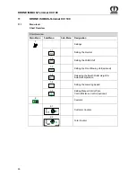
Страница 90: ...BUS Terminal CCI EasyCut EasyCut B 1000 HauptmenüsMenüebene Kurzüberblick 2014 10 08 13 39 00 180 mod_1375876254815_78 docx 1541903 1 Short Overview Short Overview Main Menu Sub Menu Sub Menu Designation 1 Settings 1 1 Auto Setting the Overcut 1 2 Auto Setting the Width Shift 1 3 Setting the Front Mowing Unit optional 1 4 Releasing the Swath Roller Height for Automatic Operation 1 6 Setting the Lo...

Страница 91: ...Sensor Test 4 4 Manual Actuator Test 4 6 Travelling Speed Display Diagnostics Motion Direction Display Diagnostics 4 7 Diagnostics Auxiliary AUX 4 9 Manual Operation without Confirmation Prompts 5 Information 6 Technician Pos 61 46 3 Layout Module Seitenumbruch 0 mod_1196175311226_0 docx 4165 1 ...

Страница 92: ...dow you get into the menu level of the machine The menu level is shown in the display Pos 61 46 7 BA Info Center CCI ISOBUS Terminal CCI BiG Pack Menüebene Überblick Hauptmenüs 5 43 mod_1275308433421_78 docx 390730 1 The menu level is divided into five main menus main menu 1 Settings main menu 2 Counters main menu 4 Service main menu 5 Info main menu 6 Fitter Select the desired main menu by pressi...

Страница 93: ...in the basic screen you get into the menu level of the machine Select main menu 1 by pressing function key or the symbol is highlighted in grey Press function key The display shows menu level 1 Settings Depending on how the machine is equipped menu level 1 Settings is divided into the following menus Auto Menu 1 1 Setting the Overcut Auto Menu 1 2 Setting the Width Shift Menu 1 3 Setting the Front...

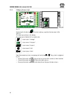
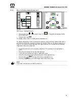
Страница 94: ...an be set for automatic operation Select the selection box A using the scroll wheel The selection box is highlighted in colour Press the scroll wheel a new input field appears Turning the scroll wheel increases or reduces the value Press the scroll wheel to apply the setting and exit the selection box Press function key to close the currently displayed menu Pressing the key for a little longer cal...

Страница 95: ... in one direction then the other so that when mowing on a slope no crop sections remain standing The upper values A can be adopted automatically diagonally for the lower values B Select the selection box A using the scroll wheel The selection box is highlighted in colour Press the scroll wheel a new input field appears Turning the scroll wheel increases or reduces the value Press the scroll wheel ...

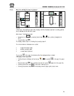
Страница 96: ...etely Mode 3 The front mowing unit is raised and lowered via the terminal The lifting process of the front mowing unit is carried out time controlled The time for lifting can be set Bringing up the Menu Main menu 1 Settings is called Select menu 1 3 by pressing function key or the symbol is highlighted in grey Press function key The display shows menu 1 3 Setting the Front Mowing Unit Changing and...

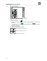
Страница 97: ... Seite 2 2 180 mod_1375796711462_78 docx 1540609 1 Setting the time for lifting for mode 3 CC000733 1 3 3 3 2 0 s 1 CC000476 Fig 56 As a pre condition mode 3 must be selected and saved Press the value 1 in the touch screen to change the time for lifting The input mask opens Increase or reduce the value 1 Confirm the entry with OK Pos 61 46 21 Layout Module Seitenumbruch 0 mod_1196175311226_0 docx ...

Страница 98: ...he swath roller height is determined by the system in automatic mode It is adapted to the speed of the cross conveyor belt Swath roller height manual setting is possible in automatic mode The symbols for the manual adjustment of the swath roller height are released for automatic mode Direct changes are possible in the main window of the display The symbol in the upper line indicates that the displ...

Страница 99: ...by pressing function key or the symbol is highlighted in grey Press function key The display shows menu 1 6 Setting the Lowering Speed The current status is displayed as a symbol 1 Highest lowering speed 3 Middle lowering speed 5 Lowest lowering speed The symbol in the upper line indicates that the displayed status is saved Changing and saving status Set the status accordingly via function key or ...

Страница 100: ...l determines the delay time for raising or lowering the lateral mowing units to the front mowing unit The delay time can be set Mode 3 Distance control determines the distance still to be covered before the lateral mowing units are raised or lowered to the front mowing unit The distance can be set Bringing up the Menu Main menu 1 Settings is called Select menu 1 7 by pressing function key or the s...

Страница 101: ...lay The input mask opens Increase or reduce the value Confirm the entry with OK Setting distance control for mode 3 CC000736 1 7 3 3 8 0 m 1 6 0 m 2 CC000476 Fig 61 1 Lifting the distance 2 Lowering the distance As a pre condition mode 3 must be selected and saved Press value 1 or 2 in the touch screen to change the distance The input mask opens Increase or reduce the value Confirm the entry with ...

Страница 102: ...00036 2 Fig 62 Calling the main menu By pressing the function key from the basic screen you get into the menu level of the machine You can select main menu 2 by pressing the function key or The symbol is highlighted in grey Press function key The display shows menu level 2 Counters Menu level 2 Counters is divided into two menus Menu 2 1 Customer counter Menu 2 2 Total counters Pos 61 46 29 Layout...

Страница 103: ...e P T O shaft is running The area counter does only appear if the appropriate parameter is released in main menu 6 Technician The area counter counts when the tractor transmits the signal forward travel to the job computer and at least one mowing unit is in use The area counter stops as soon as the tractor is stopped or no mowing unit is in use The displayed area must not correspond to the real mo...

Страница 104: ... activate it by pressing the function key The desired customer counter in this case customer counter 1 turns grey 1 The previously activated customer counter in this case customer counter 2 is no longer grey Activate deactivate the operating hours counter Meaning of the symbols h ON Operating hours counter activated h OFF Operating hours counter deactivated Pressing the function key for h ON h OFF...

Страница 105: ...er to be deleted between the two crossbars here customer counter 2 the customer counter does not need to be activated Press the function key for to set the selected customer counter here customer counter 2 to zero Deleting all customer counters Pressing the function key approx 2 sec to set all customer counters to zero Press function key to close the currently displayed menu Pressing the key for a...

Страница 106: ...rs counter h starts counting as soon as the P T O shaft is turned on The area counter counts when the tractor transmits the forward travel signal to the job computer and at least one mowing unit is in use The area counter stops as soon as the tractor is stopped or no mowing unit is in use The displayed area must not correspond to the real mowed area as it is also possible that mowing is carried ou...

Страница 107: ...you get into the menu level of the machine You can select main menu 4 with function key or The symbol is highlighted in grey Press function key The display shows menu level 4 Service Menu level 4 Service is divided into two menus menu 4 2 Manual sensor test menu 4 4 Manual actuator test Pos 61 46 41 2 Layout Module Seitenumbruch 0 mod_1196175311226_0 docx 4165 1 ...

Страница 108: ...A Info Center CCI ISOBUS Terminal CCI Swadro Swadro 2000 Hauptmenüs Hauptmenü 4 Service Menü 4 2 Sensortest Hand 4 Menü aufrufen 89 mod_1321974052838_78 docx 757569 1 Calling the menu Main menu 4 Service is called Press the function key or to enter menu 4 2 Manual sensor test The background of the selected symbol turns grey Press function key Selecting the sensor Press the function key or to selec...

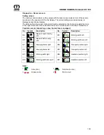
Страница 109: ...ach Ausstattung der Maschine 19 mod_1238071336628_78 docx 214010 1 Possible sensors depending on how the machine is equipped Pos 61 46 41 16 BA Info Center CCI ISOBUS Terminal CCI EasyCut EasyCut B 1000 Hauptmenüs Hauptmenüs alte Ausführung Hauptmenüs 4 ServiceAuflistung der möglichen Namursensoren EC B 1000 2014 10 14 11 54 57 94 mod_1327991793483_78 docx 792404 1 No Symbol Description No Symbol ...

Страница 110: ...7_78 docx 1030094 1 B16 Position right to approx 110 B17 Position left to approx 110 Pos 61 46 41 23 BA Info Center Sensoren Diagnose Längensystem Linearmotor 118 mod_1341998756580_78 docx 1048622 1 Diagnostics Length System Linear Motor Pos 61 46 41 24 BA Info Center Sensoren Mögliche Sensoren je nach Ausstattung der Maschine 19 mod_1238071336628_78 docx 214010 1 Possible sensors depending on how...

Страница 111: ... V 12V Term 12 14 5 V 12V Si 12 14 5 V 12V ana 12 14 5 V 8V dig 8 5 9 1 V 12V Pow2 12 14 5 V 12V Pow3 12 14 5 V Pos 61 46 41 29 BA Info Center CCI ISOBUS Terminal CCI BiG Pack Hauptmenüs ESC drücken um Menü Service 4 zu schließen bzw zum Grundbild zugelangen 44 mod_1275893530687_78 docx 393687 1 Pressing the function key closes the called up menu The display shows menu level 4 Service Pressing the...

Страница 112: ...12 Pos 61 46 41 31 Layout Module Diese Seite ist bewusst freigelassen worden 1 mod_1201783680373_78 docx 54443 1 This page has been left blank deliberately Pos 61 46 41 32 Layout Module Seitenumbruch 0 mod_1196175311226_0 docx 4165 1 ...

Страница 113: ...re moved by actuating the actuators If necessary secure the actuated machine components against unintentional lowering The actuator test must only be performed from a safe position outside the area that is affected by machine parts moved by the actuators Make certain there are no persons animals or objects in the danger zone Pos 61 46 41 35 BA Sicherheit 7 Gefahrenhinweise altGefahr Aktortest Zusa...

Страница 114: ...ISOBUS Terminal CCI EasyCut EasyCut B 1000 Hauptmenüs Hauptmenüs alte Ausführung Hauptmenüs 4 Service Menü 4 4 Aktortest Bild 94 mod_1328018144866_78 docx 794463 1 CCS00019 4 4 Fig 71 Pos 61 46 41 41 BA Info Center CCI ISOBUS Terminal CCI BiG Pack Hauptmenüs Hauptmenü 4 Service Menü 4 4 Aktortest Hand Menü aufrufen Aktor wählen 44 mod_1275888726125_78 docx 393585 1 Calling the menu Main menu 4 Ser...

Страница 115: ...ht Y 6 Float position right Y18 Fold up Y 7 Float position left Y19 Fold_up_3 Y 8 Lower mowing unit right Y20 Swing release right Y 9 Raise mowing unit right Y21 Swing release left Y10 Lower mowing unit left Y22 Working width left Y11 Raise mowing unit left Y24 Working width right Y12 Lower front mowing unit Y26 Working width reverse left Y13 Raise front mowing unit 2 valves that must be switched ...

Страница 116: ...alogue actuators diagnostics Fig 72 A current in mA can be created with the PWM value in parts per thousand Pressing the function key increases the PWM Pressing the function key decreases the PWM Possible analogue actuators No Symbol Description Y 4 Mowing unit relief right Y 5 Mowing unit relief left Y38 Cross conveyor State Actuator on Actuator off No power supply fuse is probably defective Pos ...

Страница 117: ...unction to be executed directly Pressing the function key causes the function to be executed directly No Sensor icon Description M1 Oil cooler cool clean M2 Adjust left hand swath roller linear motor M3 Adjust right hand swath roller linear motor Pos 61 46 41 51 BA Info Center Sensoren Statusanzeigen Statusanzeige digitaler Aktoren 1 2 57 mod_1295528473953_78 docx 546838 1 State Actuator on Actuat...

Страница 118: ...u 4 6 Driving speed Direction of travel indicator diagnostics Explanation of symbols 1 0 Driving forward 0 Reversing 2 25 5 km h Speed driving forward 25 5 km h Reversing speed 3 1000 RPM PTO speed 4 Parameter ISO bus evaluation selected Parameter ISO bus evaluation not selected You can use the ESCkey to close the menu currently displayed The display shows menu level 4 Service Pos 61 46 44 BA Info...

Страница 119: ...y The display shows menu 4 7 Diagnostics Auxiliary AUX Pos 61 46 47 BA Info Center CCI ISOBUS Terminal Menü 4 7 Diagnose Auxiliary AUX Menü 4 7 Diagnose Auxillary Belegung am Multifunktionshebel T2 109 mod_1335435155329_78 docx 977400 1 A figure of the multi function lever appears in the display When activating a function on the multi function lever only the assigned symbol will appear in the disp...

Страница 120: ...remove the ignition key Manual mode must only be performed from a safe position outside the area that is affected by machine parts activated by the actuators Pos 61 46 49 3 BA Info Center CCI ISOBUS Terminal CCI EasyCut EasyCut B 1000 Hauptmenüs Hauptmenüs alte Ausführung Hauptmenüs 4 Service Menü 4 9 Handbedienung ohne Sicherheitsabfragen Handbetrieb Bild 94 mod_1328262702533_78 docx 796737 1 Fig...

Страница 121: ...left lateral mowing unit Deploy left hand lateral mowing unit Lower left lateral mowing unit Retract left hand lateral mowing unit Raise front mowing unit R Retract right hand swath roller Lower front mowing unit R Deploy right hand swath roller Fold up right hand left hand lateral mowing units L Retract left hand swath roller Fold down right hand left hand lateral mowing units L Deploy left hand ...

Страница 122: ...0030 Fig 77 Calling the main menu Press function key to access the menu level via the basic screen Press function key or to select the main menu 5 The symbol is highlighted in grey Press function key The display shows menu 5 Information Page 5 1 Complete software version of the machine SW Complete software version of the machine Version of the job computer ISO ISO software version Pos 61 46 52 Lay...

Страница 123: ...echnician Calling the Main Menu CC000051 6 CC000052_1 15 6 054536 0000 Fig 78 By pressing function key in the basic screen you get into the menu level Select main menu 6 by pressing function key or The symbol is highlighted in grey Press function key Main menu 6 Technician is password protected The display shows the password query Pos 61 46 54 Layout Module Seitenumbruch 0 mod_1196175311226_0 docx...

Страница 124: ... Tasten 83 mod_1317116511667_78 docx 727008 2 1 11 7 1 Menu 9 1 Softkeys ISO terminal Note The menu 9 1 only appears on ISO terminals with less than 10 keys In menu 9 1 the basic screen for ISO terminals with less than 10 keys is set to 5 or 10 softkey buttons During the change over to 10 softkey buttons additional softkeys will be virtually included and can be reached by scrolling Note For ISO te...

Страница 125: ... screen to 10 softkey buttons The icon in the upper line indicates that the displayed status is saved Change and save status Set the desired status with the or key The icon in the top line goes out Press the key The set status is saved and the icon appears in the upper line You can use the key to close the menu currently displayed Pressing the key for a little longer calls up the basic screen Pos ...

Страница 126: ...ble in the previous terminal Note In case of a restart the system tries at first to start the last used terminal If the last used terminal is not available any longer the restart is delayed as the system is searching for a new terminal and loads the specific menus into the terminal The loading process may take a few minutes CC000484 9 Fig 81 Bring up the menu level by pressing function key from th...

Страница 127: ...sage appears in the display and an audio signal is heard at the same time constant horn signal Description possible cause and remedy are shown in the chapter entitled Alarm Messages Note All functions in the covered menu are still active The softkeys covered by the alarm message are deactivated To reset alarm To reset the alarm press function key for softkey the acoustic signal is stopped If the m...

Страница 128: ...The connection to the multi function lever is interrupted The multi function lever is not connected properly Check the wiring of the multi function lever A1 4 Undervoltage The tractor battery is defective The dynamo of the tractor is too low 12V power supply is too weak on tractor side or not correctly connected with the battery Connect KRONE connection cable directly to the battery of the tractor...

Страница 129: ...e information appears when folding up the machine into transport position Observe transport height Make certain the side guards are folded up 5 The setpoint working width right is not reached Check the parts for width shift for damage Completely retract the lateral mowing unit once 6 The setpoint working width left is not reached 11 11 L The swath roller height left is not reached Check the parts ...

Страница 130: ...width shift is smaller than 16cm when folding in the mowing unit 22 22 L Time error the process for moving cross conveyor left into the correct position takes longer than 30 seconds Perform a sensor test Check hydraulic supply 223 23 R Time error the process for moving cross conveyor right into the correct position takes longer than 30 seconds Pos 61 46 69 Layout Module Seitenumbruch 0 mod_1196175...

Страница 131: ...104 Speed of right mowing unit Sensor or line defective Perform a sensor test Check the sensor and supply line for damage 105 Speed of left mowing unit 107 Grouping below right 109 Grouping below left 111 Working width right 112 Working width zero right 113 Working width left 114 Working width zero left 118 Transport position right 119 Transport position left 136 Headland position right 137 Headla...

Страница 132: ...CCI 100 132 Pos 63 Layout Module Diese Seite ist bewusst freigelassen worden 1 mod_1201783680373_78 docx 54443 1 This page has been left blank deliberately Pos 64 Layout Module Seitenumbruch 0 mod_1196175311226_0 docx 4165 1 ...

Страница 133: ...RONE ISOBUS systems pass the ISOBUS COMPATIBILITY TEST DLG VDMA on a regular basis The operation of this machine requires at least implementation level 3 of the ISOBUS system Pos 65 3 BA Info Center Iso Bedienung Gefahr durch nicht von KRONE gelieferte Terminals Bedieneinheiten 48 mod_1286197403750_78 docx 459766 1 DANGER When using terminals and other control units which have not been delivered b...

Страница 134: ...t come in contact with the tractor wheels 12 1 1 Connection terminal to tractor Note For further details on the attachment consult the operating instructions of the ISOBUS terminal manufacturer 12 1 2 Connection tractor to machine Connect ISO plug 3 9 pole of cable set 1 with outer ISO socket 2 9 pole on tractor side Connect plug 4 7 pole of cable set 1 with socket 5 7 pole of the machine Connect ...

Страница 135: ... ISO terminals with 10 keys the functions Adjusting Approaching Width Shift and Adjusting Approaching Overcut are not available on machines without cross conveyor belt These two functions are not displayed on machines with cross conveyor belt The function Setting Approaching Width Shift and Setting Approaching Overcut can be laid on multi function lever refer to Chapter entitled ISOBUS Auxiliary F...

Страница 136: ...al mowing unit right by 8 cm Retracting lateral mowing unit right momentary action Extending lateral mowing unit right by 8 cm Extending lateral mowing unit right momentary action Retracting lateral mowing unit left by 8 cm Retracting lateral mowing unit left momentary action Extending lateral mowing unit left by 8 cm Extending lateral mowing unit left momentary action Width shift one step to the ...

Страница 137: ...Lowering lateral mowing unit left momentary action Lifting lateral mowing unit right momentary action Lifting lateral mowing unit right momentary action Lowering lateral mowing unit right momentary action Lowering lateral mowing unit right momentary action Pos 65 16 BA Info Center Iso Bedienung Tastend 119 mod_1342102507214_78 docx 1070943 1 Inching means that the function is carried out as long a...

Страница 138: ...ung EasyCut B 1000 96 mod_1328795318552_78 docx 822421 3 1 12 3 1 Example of joystick assignment for Fendt default setting Note For further guidelines please refer to the operating instructions of the terminal being used CC000545 Auto Fig 84 Pos 65 20 Layout Module Seitenumbruch 0 mod_1196175311226_0 docx 4165 1 ...

Страница 139: ...docx 798002 3 1 12 3 2 Recommended settings for a WTK multi function lever Note For further guidelines please refer to the operating instructions of the terminal being used Switch 1 on the back in upper position LED 2 lights up red 1 2 CC000540 Auto Fig 85 Pos 65 22 Layout Module Seitenumbruch 0 mod_1196175311226_0 docx 4165 1 ...

Страница 140: ...Center Iso Bedienung EasyCut Joystick Belegung_2 WTK EC B 1000 95 mod_1328522434776_78 docx 798198 1 Switch 1 on the back in lower position LED 2 lights up green Fig 86 Pos 65 24 Layout Module Seitenumbruch 0 mod_1196175311226_0 docx 4165 1 ...

Страница 141: ... Iso Bedienung EasyCut Joystick Belegung_3 WTK EC B 1000 119 mod_1342097692566_78 docx 1070665 1 Switch 1 on the back in mid position LED 2 lights up yellow 1 2 CC000544_1 Fig 87 Pos 66 Layout Module Seitenumbruch 0 mod_1196175311226_0 docx 4165 1 ...

Страница 142: ...s the provisions of the Road Traffic Licensing Regulations must be adhered to lighting identification axle loads permissible dimensions of additional housing component etc Before starting ensure that you have perfect visibility on and around the tractor and the machine Pos 67 4 BA Sicherheit 6 Überarbeitete Warnhinweise Gefahr Hochschwenken des Mähwerks in Transportstellung 2014 09 11 16 05 35 9 m...

Страница 143: ...o the transport position using the terminal the outrigger arms are fully retracted and locked and the display shows the Raise Lower front mowing unit basic dialogue After about 60 sec or on pressing function key for approx 2 sec the Raise Lower front mowing unit basic dialogue switches back to the Start up dialogue The terminal display must show the start up dialogue Note Check that the mowing uni...

Страница 144: ...e of the machine Special care should be taken when working near roads and buildings Pos 69 4 BA Bedienung EasyCut Mähen Mähen EC B 1000 B 870 100 mod_1330355620077_78 docx 892830 2 1 14 2 Mowing Swivel parking supports into transport position Move the machine to the working position Block the rear power lift Fold down the safety device Set the lateral guides correctly Before switching on the PTO m...

Страница 145: ...inst flying stones and similar objects and also prevents access to dangerous parts Because of this you must always move it to its protective position before starting work Fold the side plate s down and secure with twist locks before use Pos 69 8 BA Bedienung EasyCut Schutze Schutzeinrichtung herunterklappen Bild EC B 1000 CV 100 mod_1330441457898_78 docx 894392 1 1 ECB00038 1 2 2 Fig 89 Pos 69 9 B...

Страница 146: ... between the tractor and the machine Pos 69 13 BA Bedienung EasyCut Höheneinstellung Höheneinstellung beim Mähen über die Unterlenker am Traktor Bild EC B 1000 100 mod_1330079126391_78 docx 889547 1 Fig 90 Pos 69 14 BA Bedienung EasyCut Höheneinstellung Höheneinstellung 0 mm beim Mähen über die Unterlenker am Traktor 41 mod_1271851318445_78 docx 373526 1 During mowing the height of the headstock m...

Страница 147: ...k heben senken Arbeiten nur mit Frontmähwerk 93 mod_1327386186353_78 docx 787547 1 The front mowing unit alone can be used for partial mowing to mow small parcels of crop or narrow sections in open fields To this end the lateral mowing units must be in transport position and locked Pos 69 20 BA Info Center CCI ISOBUS Terminal CCI EasyCut EasyCut B 1000 Grundbild Frontmähwerk heben senken Grundbild...

Страница 148: ...ncts to escape from the field without injury Pos 69 24 BA Info Center CCI ISOBUS Terminal CCI EasyCut EasyCut B 1000 Grundbild Mähwerke heben senkenAbsenken aller Mähwerke von Vorgewendestellung in Arbeitsstellung abhängig vom Menü 1 7 2014 10 07 13 33 07 180 mod_1375874387618_78 docx 1541642 4 1 14 3 2 Lowering All Mowing Units from Headland Position to Working Position Lowering the lateral mowin...

Страница 149: ...t EasyCut B 1000 Grundbild Mähwerke heben senkenAnheben aller Mähwerke von Arbeitsstellung in Vorgewendestellung abhängig vom Menü 1 7 2014 10 07 13 46 53 180 mod_1375874566470_78 docx 1541671 3 1 14 4 1 Raising All Mowing Units from Working Position to Headland Position Raising the lateral mowing units to the front mowing unit depends on the set mode in menu 1 7 Setting Manual Control Distance Co...

Страница 150: ...sition Pos 69 32 BA Info Center CCI ISOBUS Terminal CCI EasyCut EasyCut B 1000 Grundbild Frontmähwerk heben senken Hinweis Tranporthöhe beachten Seitenschutze müssen angeklappt sein 96 mod_1328866631441_78 docx 823074 1 Note When the machine is folded up to the transport position information item 4 is always displayed Perform a visual check that the side protection is folded up Be aware of the tra...

Страница 151: ... mod_1327400872032_78 docx 788479 1 Before you disconnect the lateral mowing units from the tractor depressurise the hydraulic system completely so as to avoid difficulties when reconnecting the machine to the tractor the next time Pos 69 38 BA Info Center CCI ISOBUS Terminal CCI EasyCut EasyCut B 1000 Grundbild HydauliksystemGrundbild Hydrauliksystem Einführtext 2014 10 07 16 46 27 118 mod_134156...

Страница 152: ...e it so that it is protected from damp Unhitch the top suspension arm Unlock the lower guide hook of the tractor Lower the rear power lift further until the lower guide bolts are free Drive the tractor away carefully Pos 69 44 Überschriften Überschriften 2 A E Abstellen 0 mod_1199801980622_78 docx 35320 2 1 14 6 Parking Pos 69 45 BA Bedienung EasyCut Tripel Abstellen mit hochgeklappten Mähwerken B...

Страница 153: ...ed cross conveyor when the cross conveyor stopcock is closed Pos 71 4 Überschriften Überschriften 2 A E Einstellen der Schnitthöhe 0 mod_1196660879619_78 docx 9191 2 1 15 1 Adjusting the cutting height Pos 71 5 BA Einstellungen Mähwerke Schnitthöhe Schnitthöhe Bild EC B 1000 100 mod_1330082415443_78 docx 889947 1 Fig 96 Pos 71 6 BA Sicherheit 7 Gefahrenhinweise alt Sicherheitshinweise am Anfang de...

Страница 154: ...ccess to dangerous parts Because of this you must always move it to its protective position before starting work Fold the side plate s down and secure with twist locks before use Pos 71 11 BA Einstellungen Mähwerke Seitliche Schutze neue Generation CV Ausführung 116 mod_1340632285865_78 docx 1017286 3 1 15 2 1 Lateral Guards Fig 97 The height of the outer guard 1 and of the inner guard 2 can be ad...

Страница 155: ...se alt Sicherheitshinweise am Anfang des Kapitels beachten 101 mod_1330611811687_78 docx 897943 1 Observe the safety instructions at the beginning of the section Pos 71 17 BA Einstellungen Mähwerke EasyCut Pfahlsicherung Pfahlsicherung allgemein 9 mod_1220961293021_78 docx 130429 1 In order to protect the disc mower against damages during driving over obstacles it is equipped with a so called pole...

Страница 156: ...the ignition key Pos 71 24 BA Einstellungen Mähwerke Zetterdrehzahl Zetterdrehzahl Bild EC B 1000 CV 3600 3201 BM 500 BM420 Frontmähwerk 600 900 210 mod_1389161970831_78 docx 1730615 1 EC 466 0 600 900 3 1 2 Fig 99 Pos 71 25 BA Einstellungen Mähwerke Zetterdrehzahl Zetterdrehzahl einstellen 600 900 11 mod_1223613453645_78 docx 148195 1 Two tedder speeds can be set on the speed gearbox This affects...

Страница 157: ...rheitshinweise am Anfang des Kapitels beachten 101 mod_1330611811687_78 docx 897943 1 Observe the safety instructions at the beginning of the section Pos 71 31 BA Einstellungen Mähwerke Einstellung des Aufbereitungsbleches Text EC280 320 CV Q 1 59 mod_1297429715286_78 docx 558136 1 The degree of conditioning is changed by adjusting the lever 1 In the direction Degree of conditioning is increased I...

Страница 158: ...justed to the crop To do this Loosen the ring nut 1 right and left machine side Adjust the swath flaps 2 ensure that right and left machine side have the same settings to the outside A wide swath to the inside B close swath Tighten ring nut 1 Pos 71 38 BA Einstellungen Mähwerke Schwadbreite Breitablage Schwadklappenverlängerung einstellen 60 mod_1297853406559_78 docx 561524 1 The swath width can a...

Страница 159: ...te Breitablage Einstellung Breitablage Bild EC 280 320 CV Q 1 59 mod_1297432906166_78 docx 558301 1 EC 372 0 A Fig 102 Pos 71 45 BA Sicherheit 7 Gefahrenhinweise alt Sicherheitshinweise am Anfang des Kapitels beachten 101 mod_1330611811687_78 docx 897943 1 Observe the safety instructions at the beginning of the section Pos 71 46 BA Einstellungen Mähwerke Schwadbreite Breitablage Einstellung Breita...

Страница 160: ...hten 101 mod_1330611811687_78 docx 897943 1 Observe the safety instructions at the beginning of the section Pos 71 51 BA Einstellungen Mähwerke Schwadbreite Breitablage Breitverteilerblech einstellen Text 60 mod_1297859589690_78 docx 561630 1 For swathing set the wide distributor plate 2 all the way down For wide spreading the wide distributor plate can be adjusted individually to the amount of fo...

Страница 161: ...s 71 53 Layout Module Diese Seite ist bewusst freigelassen worden 1 mod_1201783680373_78 docx 54443 1 This page has been left blank deliberately Pos 71 54 Layout Module Seitenumbruch 0 mod_1196175311226_0 docx 4165 1 ...

Страница 162: ...wadbreite Breitablage Einstellung Breitablage Text EasyCut B 1000 CV Collect QFB 101 mod_1330606533977_78 docx 897345 1 Operation without the cross conveyor Move the machine to the working position Switch off the PTO and then the tractor engine secure the tractor against rolling and remove the ignition key Remove the deflector plates 2 from the brackets 1 and put to one side Start the tractor and ...

Страница 163: ...erke Schwadbreite Breitablage Einstellung Breitablage Querförderband wird eingesetzt 2014 03 18 08 13 33 101 mod_1330618950304_78 docx 898685 1 Cross conveyor in use For operation with activated cross conveyor we recommend removing the deflector plates Move the machine to the working position Raise the cross conveyor over the terminal Switch off the PTO and then the tractor engine secure the tract...

Страница 164: ... side panel folds up and that foreign objects are slung away Therefore it is very important to ensure before every use that the side panel 1 of the machine is folded down and that the locking 2 is secured The side panel 2 must be adjusted in that way that the side panel 1 folds down when swivelling the machine from transport position to working position and that it is secured by the locking 2 the ...

Страница 165: ...ellen des Rollenabstandes EasyCut CR Ausführung 193 mod_1383229458078_78 docx 1647015 1 EC 452 0 2 1 CRI 0 001 Fig 106 The roller distance X can be adjusted by means of the screw 1 right and left side of the machine The dimension X 2 mm must not be below this level to avoid high wear on the rollers Loosen the nuts 2 Increasing the distance X Rotate the screw 1 in the direction I to increase the di...

Страница 166: ... rolling and remove the ignition key Release the screw type bearings 1 at the front and rear of the running roller Unclamp the conveyor belt by releasing the clamping screws 4 5 at the front and rear of the running roller Raise the cross conveyor over the terminal Mark the conveyor belt above and below at intervals of x 1000 mm Use the adjustment screws 4 5 to tighten the conveyor belt until the m...

Страница 167: ...trial run after each adjustment and check the markings Adjustments may only be made on one side That means that the clamping screw that was previously tightened must be released again to avoid overtensioning the conveyor belt Once the conveyor belt is properly set the markings must lie between 1005 mm and 1008 mm Provided the individual marking measurements remain within the range 1005 mm to 1008 ...

Страница 168: ...never a blade is changed also inspect the fasteners and replace them if necessary Pos 76 3 Überschriften Überschriften 3 P T Probelauf 0 mod_1196833698843_78 docx 15023 3 1 16 1 1 Test run Pos 76 4 BA Sicherheit 7 Gefahrenhinweise alt Mähwerke Gefahr Probelauf Mehrzahl 0 mod_1196782825187_78 docx 14889 1 Danger Testing the machine after repair maintenance or cleaning work and after technical inter...

Страница 169: ...daily Once after 50 hours Every 50 hours Every 200 hours Cutter bar Oil level check X X Oil change not required All gearboxes Oil level check X X Oil change X X Checking the cutter blades X X Check the retaining bolts for cutter blades X X Check the material thickness of the leaf springs with blade quick fit device design X X Cutting disc blade drum X X Linings on the cutter bar X Tighten the scre...

Страница 170: ...e screw A Ø 5 6 6 8 8 8 10 9 12 9 MA Nm M 4 2 2 3 4 4 5 1 M 5 4 5 5 9 8 7 10 M 6 7 6 10 15 18 M 8 18 25 36 43 M 10 29 37 49 72 84 M12 42 64 85 125 145 M14 100 135 200 235 M14x1 5 145 215 255 M 16 160 210 310 365 M16x1 5 225 330 390 M 20 425 610 710 M 24 730 1050 1220 M 24x1 5 350 M 24x2 800 1150 1350 M 27 1100 1550 1800 M 27x2 1150 1650 1950 M30 1450 2100 2450 NOTE The table above does not apply t...

Страница 171: ...9 35 M 10 23 39 58 67 M 12 34 68 100 116 M 14 108 160 188 M 16 168 248 292 M 20 340 488 568 A BM 400 0234 NOTE The table above applies only to countersunk screws with hexagonal socket heads and metric threading that are tightened by the hexagonal socket head Pos 76 17 Überschriften Überschriften 3 A E A Abweichendes Drehmoment 0 mod_1196950054171_78 docx 15312 3 1 16 5 1 Deviating Torque Pos 76 18...

Страница 172: ...ung optional 4 mod_1213097920976_78 docx 86356 2 1 16 6 Rotary hub with shear fuse optional Pos 78 2 BA Wartung Mähwerke Schersicherung Bild Mähholm Aufstellung EC B 1000 99 mod_1330073924871_78 docx 889302 1 Fig 109 Pos 78 3 Layout Module Seitenumbruch 0 mod_1196175311226_0 docx 4165 1 ...

Страница 173: ...ying groove Pos 78 6 BA Wartung Mähwerke Schersicherung Beschreibung Schersicherung RE LE 99 mod_1330074896634_78 docx 889358 1 For protection against overload on the mowing units the rotary hubs 1 are secured with nuts 2 and shear pins 3 If the machine strikes obstacles for example stones the 2 shear pins in the rotary hub will be sheared off The rotary hub and nut turn upward on the pinion shaft...

Страница 174: ... of the bearing housing not observed Effect Damage to the machine Right rotating RE RZ cutting discs and drums always have right handed pinion shafts and nuts no groove mark on the pinion shaft and nut Left rotating LE LZ cutting discs and drums always have left handed pinion shafts and nuts with groove mark on the pinion shaft and nut 1 3 2 8 7 3 4 c d a 9 b EC 255 0 10 3a 3a 3a Fig 110 ...

Страница 175: ... new shear pins 3 through the hub 1 and shaft 4 Note Note the position of the shear pins Drive the shear pins 3 into the hole from outside until the end of the pin reaches the surface of the hub d he slots of the shear pins 3 must be mounted facing each other horizontally see detail I Install the nut 2 using the special key 10 included with delivery tighten to a tightening torque of 300 Nm Install...

Страница 176: ...chdruckfilter bei Komfort_Hydraulik Bild_EC B 1000 100 mod_1330444609265_78 docx 894677 1 Fig 111 Pos 81 6 BA Wartung Hochdruckfilter Filterelement wechseln 26 mod_1245841608710_78 docx 264205 1 Replacing the Filter Element Pos 81 7 BA Wartung Hochdruckfilter Ort HochdruckfilterHydraulikkreislauf EC B 1000 100 mod_1330445065697_78 docx 894748 1 The hydraulic system filter 6 is at the front on the ...

Страница 177: ...ade while the machine is depressurised Pos 83 1 5 Überschriften Überschriften 3 A E B Betrieb der Maschine ohne LS Load Sensing Anschluss 91 mod_1326699351886_78 docx 780162 3 1 17 2 1 Operating the Machine without LS Load Sensing Connection Pos 83 1 6 BA Wartung Load Sensing Systemschraube 1 ganz herausdrehen 63 mod_1299739012796_78 docx 575371 1 Unscrew the system screw 1 as far as it will go fo...

Страница 178: ...1000 Not Handbetätigung EasyCut B 1000 98 mod_1329718677141_78 docx 880005 1 The electromagnetic valve block I is at the front on the three point block of the machine In the event the electrical system should fail completely the valves are equipped with an Emergency manual activation All valves are activated by screwing in the setting screw Pos 83 5 Layout Module Seitenumbruch 0 mod_1196175311226_...

Страница 179: ...tion is not permitted during operation on the closed hydraulic system PB LS For emergency manual operation change the machine s hydraulic system hydraulic lines to operation via double action control unit by means of the two hydraulic plugs supplied Disconnect the LS signal line and place it in the bracket provided on the machine Do not activate the control unit until you have left the danger area...

Страница 180: ...76 2 1 17 5 Comfort Hydraulic Block Diagram Pos 83 13 Abkürzungen Abkürzungen sprachneutral EasyCut EasyCut B 1000 CV Colllect 99 mod_1330072969727_0 docx 889217 1 EasyCut B 1000 CV Collect Pos 83 14 BA Wartung Load Sensing EasyCut B 1000 Schaubild Hydraulikblock Komfort EasyCut B 1000 mit Collect 98 mod_1329490914691_78 docx 879948 1 Fig 113 ...

Страница 181: ... Y11 2 Fold the left hand lateral mowing unit in headland position Y09 3 Lower the left hand cross conveyor Y1 Y16 1 Y16 2 4 Lower the right hand cross conveyor Y1 Y17 1 Y17 2 5 Deploy the left hand lateral mowing unit Y2 Y24 1 Y24 2 6 Deploy the right hand lateral mowing unit Y2 Y22 1 Y22 2 7 Fold the lateral mowing units from the headland position to transport position Y2 Y18 1 Y18 2 Y19 8 Retra...

Страница 182: ...llowing table very exactly in order to raise the machine to transport position After each step screw the setting screws out again 1 Fold the left hand lateral mowing unit in headland position Y11 2 Fold the right hand lateral mowing unit in headland position Y09 3 Deploy the left hand lateral mowing unit Y2 Y24 1 Y24 2 4 Deploy the right hand lateral mowing unit Y2 Y22 1 Y22 2 5 Fold the lateral m...

Страница 183: ...SAE 90 Screw the check screw 1 back in Pos 86 4 BA Wartung Ölkontrolle_Wechsel Ölwechsel_ALT Ölwechsel Version3 1 mod_1201255900073_78 docx 52826 1 Oil change For time intervals see Chapter Oil Level Check and Oil Change Intervals Gearboxes Screw out the oil drain plug 2 Collect the used oil in a suitable drip pan Screw in the oil drain plug 2 Top up the oil 3 oil level up to hole 1 Screw the insp...

Страница 184: ...sel Ölwechsel bis mitte Schauglas 83 mod_1317706975865_78 docx 729414 1 Oil change For time intervals see Chapter entitled Oil Level Check and Oil Change Intervals Gearboxes Screw out the oil drain plug 2 Collect the used oil in a suitable drip pan Screw in the oil drain plug 2 Top up the oil 3 the oil level must be visible at least halfway up the inspection window 1 Pos 88 5 BA Wartung Ölkontroll...

Страница 185: ... 8 BA Wartung Ölkontrolle_Wechsel Ölkontrolle Ölwechsel Intervall siehe Kapitel Wartung Wartungstabelle 134 mod_1350483605921_78 docx 1188115 1 Interval for oil level check and oil change refer to chapter Maintenance Maintenance Table Pos 90 9 BA Wartung Ölkontrolle_Wechsel Ölkontrolle NEU über Kontrollschraube 140 mod_1355141753680_78 docx 1244582 1 Oil level check Screw out inspection screw Oil ...

Страница 186: ...tung Ölkontrolle_Wechsel Ölkontrolle Ölwechsel Intervall siehe Kapitel Wartung Wartungstabelle 134 mod_1350483605921_78 docx 1188115 1 Interval for oil level check and oil change refer to chapter Maintenance Maintenance Table Pos 92 9 BA Wartung Ölkontrolle_Wechsel Ölkontrolle NEU über Kontrollschraube ohne Einfüllschraube 158 mod_1364483633589_78 docx 1391741 1 Oil level check Screw out inspectio...

Страница 187: ...kontrolle Ölwechsel Intervall siehe Kapitel Wartung Wartungstabelle 134 mod_1350483605921_78 docx 1188115 1 Interval for oil level check and oil change refer to chapter Maintenance Maintenance Table Pos 94 8 BA Wartung Ölkontrolle_Wechsel Ölkontrolle NEU über Kontrollschraube 140 mod_1355141753680_78 docx 1244582 1 Oil level check Screw out inspection screw Oil level up to control hole If the oil ...

Страница 188: ...obody should be in the danger zone around the machine Pos 96 6 BA Sicherheit 7 Gefahrenhinweise alt Mähwerke Gefahr Schnell rotierende Messerteller Messertrommeln_1 0 mod_1197017696736_78 docx 16001 1 Danger Rapidly rotating cutting discs blade drums Effect Danger to life or serious injuries Switch off the engine and remove the ignition key The cutting discs blade drums continue to run Do not leav...

Страница 189: ... bolts every time you change the blades or after contact with foreign objects Immediately replace missing or damaged cutter blades and cutter blade retainers Pos 99 3 BA Wartung Mähwerke Nach Beendigung Schutz in Schutzstellung bringen Bild EC B 1000 102 mod_1331031746319_78 docx 901894 1 ECB00055 1 Fig 121 Pos 99 4 BA Wartung Mähwerke Nach Beendigung Schutz in Schutzstellung bringen Text EC F 320...

Страница 190: ...98_78 docx 72588 1 Danger Insufficient thickness of material on the cutter blades Effect Danger to life or serious injuries The cutter blades must be replaced at the latest when the wear limit is reached see mark 1 on the cutter blade dimension a less than or equal to 7 mm Pos 99 9 BA Wartung Mähwerke Mähklingen beidseitig verwenbar_neu 3 mod_1204728012601_78 docx 72608 1 a EC 253 0 1 Fig 122 Note...

Страница 191: ...st point EC 240 0 min 14 mm Fig 123 Pos 99 12 BA Wartung Mähwerke Messerschraub Messerschnellverschluss Messerschnellverschluss Haltebolzen 14mm 0 mod_1197268087875_78 docx 16444 3 1 19 1 3 Blade Quick Fit Device Danger Insufficient thickness of material on the retaining bolts Effect Danger to life or serious injuries At every blade changing check the thickness of the holding bolts material Damage...

Страница 192: ...n the leaf springs Effect Danger to life or serious injuries Check the leaf springs for damages at least once a day or after contact with foreign objects The abrasion limit of the leaf springs will be achieved if the application seam 1 is worn on one point EC 225 0 1 1 Fig 125 Note Use only original Krone spare parts to replace the leaf springs Pos 99 15 Layout Module Seitenumbruch 0 mod_119617531...

Страница 193: ...Discs Blade Drums Effect Danger to life or serious injuries Check the cutting discs or blade drums for damages at least once per day or after contact with foreign objects In case of deformed cuttings discs or drums the dimension of A 48 mm must never be exceeded EC 0 211 A 1 Fig 126 Note The cutting discs or drums must be replaced by Original Krone spare parts only Pos 99 17 Layout Module Seitenum...

Страница 194: ... drums Effect Danger to life or serious injuries The abrasion limit 2 will be achieved if the min material thickness of 3 mm is no longer given EC 226 0 2 2 Fig 127 Note If cutting discs or blade drums show deformations or wear in form of abrasions 2 or similar these components have to be replaced by Original Krone spare parts Pos 99 19 Layout Module Seitenumbruch 0 mod_1196175311226_0 docx 4165 1...

Страница 195: ...lade drums continue to run Do not leave the driver s cab until the cutting discs blade drums have come to a complete stop Pos 99 22 BA Sicherheit 7 Gefahrenhinweise alt Mähwerke Gefahr Sich lösende Mähklingen 0 mod_1197269483265_78 docx 16540 1 Danger Cutter blades coming loose Effect Danger to life or serious injuries After changing the blades check that they fit perfectly and that they can move ...

Страница 196: ...ting disc Place the locknut 4 on the retaining bolt from above and tighten it firmly tightening torque refer to chapter Torques Repeat the process for all blades After fitting the blades fold the safety device down again Note The cutter blades of anticlockwise rotating cutting discs blade drums are different to those of clockwise rotating ones Make certain the direction of rotation is correct when...

Страница 197: ...de a new blade 2 onto the retaining bolt and allow the blade key to return upwards After fitting the blades fold the protective device down again Note The cutter blades of anticlockwise rotating cutting discs blade drums are different than those of clockwise rotating ones Make certain the direction of rotation is correct when installing The arrow on the cutter blades must match the direction of ro...

Страница 198: ...erial to the cutter bar material and to the lining or carry out a trial welding if necessary EC 0 012 Fig 130 Open the welding seams of the old lining Remove the lining Deburr the contact surface EC 252 0 Fig 131 Adapt the new lining 3 Weld short I seams on the upper surface of the cutter bar in the areas marked 1 each should be approx 30 mm Do not weld the edges 2 On the lower surface of the cutt...

Страница 199: ...ractor engine and remove the ignition key Secure the tractor against accidental start up and against rolling Switch off the PTO and disengage it After repair maintenance cleaning work or technical modifications are complete mount all protective coverings and safety devices again properly Avoid skin contact with oils greases cleaning agents and solvents In the event of injuries or burns due to oils...

Страница 200: ...495 2 1 20 3 Lubrication Chart Pos 102 8 Abkürzungen Abkürzungen sprachneutral EasyCut EasyCut B 1000 CV 99 mod_1330072906572_0 docx 889189 1 EasyCut B 1000 CV Pos 102 9 BA Wartung Mähwerke EasyCut AM Mähwerke Schmierpläne Schmierplan EC B 1000 CV 103 mod_1332148116993_78 docx 939233 1 ECB00061 Fig 133 EasyCut B 1000 CV ...

Страница 201: ...Maintenance lubrication chart 201 1 50h 2 50h 3 50h 4 50h 5 100h 6 50h 7 50h Pos 102 10 Layout Module Seitenumbruch 0 mod_1196175311226_0 docx 4165 1 ...

Страница 202: ...ral EasyCut EasyCut B 1000 CV Colllect 99 mod_1330072969727_0 docx 889217 1 EasyCut B 1000 CV Collect Pos 102 12 BA Wartung Mähwerke EasyCut AM Mähwerke Schmierpläne Schmierplan EC B 1000 CV Collect 100 mod_1330512062487_78 docx 895397 1 ECB00044 Fig 134 EasyCut B 1000 CV Collect ...

Страница 203: ...Maintenance lubrication chart 203 1 50h 2 50h 3 50h 4 50h 5 100h 6 50h 7 50h 8 100h 9 100h 10 100h Pos 102 13 Layout Module Seitenumbruch 0 mod_1196175311226_0 docx 4165 1 ...

Страница 204: ...ngen sprachneutral EasyCut EasyCut B 1000 CR 211 mod_1389617597232_0 docx 1737686 1 EasyCut B 1000 CR Pos 102 15 BA Wartung Mähwerke EasyCut AM Mähwerke Schmierpläne Schmierplan EC B 1000 CR 211 mod_1389617708638_78 docx 1737894 1 ECB00073 Fig 135 EasyCut B 1000 CR ...

Страница 205: ...Maintenance lubrication chart 205 1 50h 2 50h 3 50h 4 50h 5 50h 6 50h 7 50h 8 50h Pos 102 16 Layout Module Seitenumbruch 0 mod_1196175311226_0 docx 4165 1 ...

Страница 206: ...al EasyCut EasyCut B 1000 CR Colllect 211 mod_1389617598451_0 docx 1737835 1 EasyCut B 1000 CR Collect Pos 102 18 BA Wartung Mähwerke EasyCut AM Mähwerke Schmierpläne Schmierplan EC B 1000 CR Collect 211 mod_1389617732809_78 docx 1737923 1 ECB00074 Fig 136 EasyCut B 1000 CR Collect ...

Страница 207: ...Maintenance lubrication chart 207 1 50h 2 50h 3 50h 4 50h 5 50h 6 50h 7 50h 8 100h 9 100h 10 100h 11 50h Pos 103 Layout Module Seitenumbruch 0 mod_1196175311226_0 docx 4165 1 ...

Страница 208: ... 106 Abkürzungen Abkürzungen sprachneutral EasyCut EasyCut B 1000 CV 99 mod_1330072906572_0 docx 889189 1 EasyCut B 1000 CV Pos 107 BA Wartung Mähwerke EasyCut AM Mähwerke Lage der Sensoren Lage der Sensoren EC B 1000 CV 103 mod_1332148843378_78 docx 939295 1 ECB00062 B36 B37 Fig 137 EasyCut B 1000 CV 1 B36 Headland position right B37 Headland position left 2 B16 Position of right hand mowing unit...

Страница 209: ...Working width right zero B14 Working width left zero 5 B4 Speed of right hand mowing unit B5 Speed of left hand mowing unit 6 B11 Working width right B13 Working width left Pos 108 Layout Module Seitenumbruch 0 mod_1196175311226_0 docx 4165 1 ...

Страница 210: ...ect Pos 110 BA Wartung Mähwerke EasyCut AM Mähwerke Lage der Sensoren Lage der Sensoren EC B 1000 CV Collect 100 mod_1330528606595_78 docx 896220 1 Fig 138 EasyCut B 1000 CV Collect 1 B36 Headland position right B37 Headland position left 2 B16 Position of right hand mowing unit B17 Position of left hand mowing unit 3 B18 Transport position right B19 Transport position left ...

Страница 211: ...t hand mowing unit B5 Speed of left hand mowing unit 6 B7 Cross conveyor below right B9 Cross conveyor below left 7 B11 Working width right B13 Working width left 8 BM3 Position of right hand swath roller BM4 Position of left hand swath roller Pos 111 Layout Module Seitenumbruch 0 mod_1196175311226_0 docx 4165 1 ...

Страница 212: ...14 BA Wartung Sensoren Anzugsdrehmoment Namursensor 10 Nm 101 mod_1330933143264_78 docx 899752 1 The tightening torque for all Namur sensors is 10 Nm Pos 115 BA Wartung Sensoren Namursensor d 30 mm a 4mm 101 mod_1330933066304_78 docx 899724 4 1 21 1 1 2 Namur sensor d 30 mm a BPXC0172 2 1 3 Fig 140 The dimension between the encoder 2 and the sensor 1 must be a 4 mm Setting Loosen the nuts on eithe...

Страница 213: ...y Secure the tractor against accidental start up and against rolling Switch off the PTO and disengage it After repair maintenance cleaning work or technical modifications are complete mount all protective coverings and safety devices again properly Avoid skin contact with oils greases cleaning agents and solvents In the event of injuries or burns due to oils cleaning agents or solvents contact a d...

Страница 214: ...ut EasyCut B 1000 Grundbild AutomatikbetriebQFB rechts heben senken 2014 10 08 11 17 25 93 mod_1327477554523_78 docx 789766 3 1 22 4 1 Raise Lower right hand cross conveyor Pressing the function key for once lowers the cross conveyor to the working position the cross conveyor drive starts automatically Pressing the function key for once lifts the cross conveyor out of the working position the cros...

Страница 215: ...nd hold the function key for to raise the preselected cross conveyor Press and hold the function key for to lower the preselected cross conveyor Pos 120 14 BA Info Center CCI ISOBUS Terminal CCI EasyCut EasyCut B 1000 Grundbild QuerförderbandQFB gleichzeitig heben senken 2014 10 07 16 23 03 93 mod_1327395688547_78 docx 787886 3 1 22 5 3 Raise Lower both cross conveyors simultaneously Preselect the...

Страница 216: ...es to avoid the risk of injury Escaping high pressure fluids can penetrate the skin and cause serious injury Therefore you must depressurise the system before disconnecting lines Hydraulic oil escaping from a small opening can barely be seen Because of this you should use a piece of cardboard or something similar when searching for leaks Protect your hands and body If any fluid penetrates the skin...

Страница 217: ...e oils Pos 120 25 Überschriften Überschriften 3 K O Ölbehälter 10 mod_1222335200051_78 docx 140543 3 1 22 7 2 Oil Tank Pos 120 26 BA Sonderausstatung EasyCut AM Mähwerke Querförderer Ölbehälter Bild EC B 1000 CV Collect 101 mod_1330683086870_78 docx 899216 1 Fig 145 Pos 120 27 BA Sonderausstatung EasyCut AM Mähwerke Querförderer Bordhydraulik allgemein 10 mod_1222335092723_78 docx 140522 1 Pressur...

Страница 218: ...ventilation filter 2 and insert it again completely Pull out the ventilation filter 2 again The oil level must lie between the min and max mark Top off with hydraulic oil if necessary Screw in and tighten the ventilation filter 2 Pos 120 33 Überschriften Überschriften 3 K O Ölwechsel 0 mod_1197021941955_78 docx 16139 3 1 22 7 4 Oil change Pos 120 34 BA Sonderausstatung EasyCut AM Mähwerke Querförd...

Страница 219: ...hanging the filter Properly dispose of filter cartridge that was removed Replace the hydraulic oil filter before every season but at least once year Unscrew the screw cover 1 Lift the filter insert 2 and allow hydraulic oil to drip out Remove the filter insert and dispose of it properly Moisten the seal surface of the new filter insert with oil and set it in place Tighten the screw cover 1 Pos 120...

Страница 220: ...s WARNING Cleaning with high pressure equipment Effect Loss of eyesight Keep people well away from the working area Wear suitable work clothes to perform cleaning jobs with high pressure equipment for example eye protection Note Clean the cross conveyors only at low pressure and using plenty of water Never use cleaning agents After cleaning lubricate the bearings Fig 148 ...

Страница 221: ...erminal Switch off the PTO and then the tractor engine secure the tractor against rolling and remove the ignition key Close the stopcock on the cross conveyor Clean the locations a to f with the high pressure cleaner Attach the plastic covers Mount the deflector plate retainers Open the stopcock on the cross conveyor Pos 121 Layout Module Seitenumbruch 0 mod_1196175311226_0 docx 4165 1 ...

Страница 222: ...n the bearing rings of the guard tubes Pos 122 2 4 BA Einlagerung Alle Gelenkstellen einölen 70 mod_1305633347429_78 docx 638432 1 Oil all joint points Pos 122 2 5 BA Einlagerung Lackschäden ausbessern blanke Stellen gründlich mit Rostschutzmittel konservieren 70 mod_1305630900253_78 docx 638320 1 Touch up damaged paint and preserve all uncoated areas thoroughly with rust protection agent Pos 122 ...

Страница 223: ... against rolling Switch off the PTO and disengage it After repair maintenance cleaning work or technical modifications are complete mount all protective coverings and safety devices again properly Avoid skin contact with oils greases cleaning agents and solvents In the event of injuries or burns due to oils cleaning agents or solvents contact a doctor immediately All other safety instructions must...

Страница 224: ...rtain they are tight or retighten them if necessary Check all electrical connection cables and the lighting Repair or replace if necessary Check the entire setting of the machine and correct if necessary Re read the operating instructions thoroughly Note Use vegetable oils and greases Pos 122 10 BA Einlagerung Reibkupplung Reibkupplung lüften vor der Saison 3 mod_1204731645242_78 docx 72787 1 Vent...

Страница 225: ...x 72885 1 EC 257 0 1 2 Fig 149 The friction clutch protects the tractor and the machine against damage It is designed with a permanently adjusted turning torque MR The torque is applied on the housing of the friction clutch 2 Venting the friction clutch Tighten the four nuts 1 Block the machine and move the friction clutch manually to the point where it slips through Loosen the nuts again Pos 122 ...

Страница 226: ...3544391539_78 docx 147914 2 1 25 1 Electrical circuit diagram Pos 124 3 BA Anhang EasyCut Schaltpläne EC B 1000 CV EC B 1000 CV Collect 104 mod_1332332300764_78 docx 943216 1 You will find the circuit diagrams listed below in the Appendix 1 Circuit diagram with cross conveyor belt 150 100 745 2 Circuit diagram without cross conveyor belt 150 100 745 Ende der Liste für Textmarke Inhalt ...

Страница 227: ... 1 3 2 0 1 3 2 0 2 M 1Q 1 M 0P M34 M17Q M17Q 1 M 1Q 2 M 1Q M M 1 M 1P 2 M 1P M0Q UcaT 06 M 17P M 17P 86C C9 86C A K J HHO0K C9O X KO X KO60 C9O60 86C A 86C 0 1 2 3 0 1 2 3 0 1 2 3 0 6 HD Qca bT X P 88 3 I I 1 f 3 M0P M0 7Q DW M 2 M 1 M 30 M 31 G1 DW PSP_bT RPQ T U HD 9 C a RZTb Pb bWT b PRb R TRbX b PRb QPbbT g BPaaT K R b RX RcXb K SXdXSTS X b P VcPVT R STa P SeP T C b Hb _5 aXbT X aRWP baXV P Uj...

Страница 228: ... 6 0 60 0 61 1 6 1 61 1 60 1 6 2 2 4 2 1 62 1 6 1 6 0 6 0 6 6 6 6 93 93 0 63 1 63 3 4 4 3 M Q M Q M Q HHO0K KO X C9O X K J 86C 86C A C9 M O4 M O 3 M O 4 M O M O 0 M O3 M O 1 M O 2 M O 2 M O M O M O 0 M O M O M O 2 M O 4 M O M O M O M O 0 M O0 M O1 M O M O 3 M O M O 4 M O 9 GFO 9 GFO1 9 GFO2 9 GFO 9 GFO 9 O 9 O 6C6 GFO 6C6 GFO OHIGDBO 7ELBHIGO 7ELBHIGO ELBA6O ELBA6O3 A6O 70 a_TTS eX V c Xb TUb 7 e ...

Страница 229: ...O3 M O M O M O M O M O M O1 M O M O 1 06 4 1 4 0 2 0 2 1 3 3 3 0 0 62 1 6 0 6 1 6 0 6 2 2 M O M O M O 0 M O 4 M O4 M O M O M O0 M O M O M O M O 2 M O 1 M O 0 M O 3 M O 4 M O 3 M O M O 3 M O M O2 M O 0 M O 2 M O 2 9 GFO 9 O BJAI O BJAI O HIGDBO HIGDBO HIGDBO ELBA6O ELBA6O ELBA6O0 ELBA6O1 ELBA6O2 ELBA6O4 ELBA6O ELBA6O A6O A6O A6O 7 4 b P a_ b _ aXbX TUb 7 U b eT Pb bWT b _ 7 RWP VT _ Taac T N eX V c...

Страница 230: ...T U T_PX X V M O 4 M O 0 86C A 86C Qca 86C 86C Qca Qcbb c_ 3 0K aT a 1 3 0K aT a 2 3 0K aT a 3 M O 3 M O M O 0 M O M O M O 6 6 60 60 61 M O M O M O M O M O M O M O 4 M O M O M O M O M O 2 M O 4 M O M O M O 1 M O 0 M O M O M O M O 3 M O 1 M O 2 M O 2 M O 3 M O 1 M O 0 M O 2 M O M O 0 M O 1 0 6 6 6 60 61 63 64 1 2 3 6 62 TaT dT 9O TaT dT N 2 aePbW V c_X V XVWb B AjUbT TaT dT TaT dT TaT dT TaT dT TaT...

Страница 231: ... M O 2 7 O M O 4 7 4 b P a_ b _ aXbX TUb B M7 4P M7 4P 7 4O M O M O 70 a_TTS eX V c Xb TUb 9 GFO 9 6 M Q M O 1 7 e ZX V eXSbW TUb 9 GFO 9 6 M Q M O 3 7 e ZX V eXSbW hT TUb 9 GFO 9 6 M Q 7 2 _ aXbX TUb AD76J 0K k 2 M7 2Q M7 2Q M O 7 2 _ aXbX TUb 6C6 GFO 9 6 M Q 7 2O M O 0 7 2O M O M O 4 7 4 b P a_ b _ aXbX TUb 9 O 9 6 M Q MABQ MABQ MABQ MABQ MABP MABP MABP MABP 7 2 WTPS P S TUb B M7 2P M7 2P 7a 8 6...

Страница 232: ... M7 P M7 P M7 P M72P M7 P M7 P 7 O M O 1 72O M O4 7 O M O 7 O M O 7 3 b P a_ b _ aXbX XVWb B M7 3P M7 3P 7 3O M O M O 7 e ZX V eXSbW XVWb 9 O 3 92 6 M Q M O 7 e ZX V eXSbW hT XVWb 9 O 4 92 6 M Q M O 7 3 b P a_ b _ aXbX XVWb 9 GFO4 91 6 M Q 7 1 _ aXbX XVWb AD76J 0K k 2 7 1O M O 7 1O M O M7 1Q M7 1Q M Q M O 7 1 _ aXbX XVWb 6C6 GFO 92 6 MGBQ MGBQ MGBQ MGBQ MGBP MGBP MGBP MGBP 7 1 WTPS P S XVWb B M7 1...

Страница 233: ...XVWb ELBA6O2 9 6 M O N eX V c Xb T XTdT XVWb HIGDBO 9 6 M O N0 eX V c Xb T XTdT TUb HIGDBO 9 6 M Q M Q M Q M Q M Q N2 U Pb _ aXbX TUb N1 U Pb _ aXbX XVWb N0 eX V c Xb T XTdT TUb N eX V c Xb T XTdT XVWb N Uc RbX dP dT Tb PRb N Uc RbX dP dT TfbT S N2O M O 2 N1O M O M O 1 N2 U Pb _ aXbX TUb A6O 9 6 M Q N3 eX V c Xb eT XVWb N3O M O M O N3 eX V c Xb eT XVWb ELBA6O4 9 6 M Q MN Q MN Q MN Q MN Q MN Q MN Q...

Страница 234: ...M Q M Q N eX V c Xb eT U b N eX V c Xb XUb TUb 1 1 L N4 eX V c Xb XUb XVWb 1 1 L N O M O 4 N O M O 2 N O M O2 M O N eX V c Xb XUb U b A6O 9 6 M Q N eX V c Xb XUb U b N O M O 0 N eX V c Xb eT TUb N4O M O 2 N 1 aePbW V c_X V TUb M O 1 N4 eX V c Xb XUb XVWb ELBA6O 92 6 M Q M O 6 N 1 aePbW V c_X V TUb 3 9 60 M60 Q N 1OM60O 2 N 1 aePbW V c_X V TUb M 0 M 1 MN4Q MN4Q MN Q MN Q MN Q MN Q MN Q MN Q MN Q MN...

Страница 235: ...W TUb N e ZX V eXSbW TUb N O M O M 3 M N 3 U S N 3 U S M M 0 N 3O M O 1 MN 3 Q MN 3 Q M O N 3 U S U S 7ELBHIGO 9 6 M Q N 2 aePbW V c_X V XVWb M60 Q M O 6 N 2 aePbW V c_X V XVWb 4 9 60 N 2OM60O 4 N 2 HRWePShcaP T UjW c V5 XVWb M 2 M 3 M Q M O N 4 U S 7ELBHIGO 9 6 N 3 U S N 4O M O 2 MN 2 Q MN 2 MN 2 MN 3 Q MN 3 Q MN Q MN Q MN Q MN Q M O3 N ET Sc c U P T U TT TUb ELBA6O0 9 6 M Q N O M O4 M O N ET Sc ...

Страница 236: ...bW RWP VT dT XVWb ELBA6O 92 6 N 3 bW bb T dP dT R aa R dTg MN 3Q MN 3Q G 9 LXST abP S DW 9O OG M60 Q M O 9O 9 60 M O 9O 91 61 9O OG M61 Q G 9 LXST abP S DW N e ZX V eXSbW XVWb N e ZX V eXSbW XVWb N O M O M 4 M M O N e ZX V eXSbW XVWb 7ELBHIGO 92 6 M Q MN 3 Q MN 3 Q MN 3 Q MN 3 Q MN 1Q MN 1Q M O N 3 bW bb T dP dT R aa R dTg ELBA6O 9 6 M Q MN Q MN Q MN Q MN Q M O N 3 bW bb T dP dT R aa R dTg OHIGDBO...

Страница 237: ...M O 6 B AjUbT 9 60 M60 Q M7B Q M7B Q M7B Q M7B Q M7B Q M7B Q M7B Q M7B Q B B aePbW T PSYcabX V b XVWb D_bX M7B P M7B P M7B P M7B P M7B P M7B P M7B P M7B P 7B 7B _ aXbX aePbW T XVWb 8GJBFE M O 6 B aePbW T PSYcabX V b TUb 92 61 M O 4 6 B aePbW T PSYcabX V b TUb 93 61 M O 3 6 B aePbW T PSYcabX V b XVWb 93 61 M O 0 6 B aePbW T PSYcabX V b XVWb 93 61 M61 Q M61 Q M61 Q M61 Q 7B OM61O 4 7B OM61O 7B OM61O...

Страница 238: ... EJ EF 0 5 IM 3KJ 2 3 XVWbX V 1 2 3 eTaaT ZPT Y 4 4 89 5 4 6 89 4 89 5 4 6 89 0 8 0 M 2 M 43 M 44 M P M P M Q M Q M Q M Q M M Q M Q 4 5 4 6 89 1 2 3 4 5 4 6 89 1 2 3 7 4 96 1 2 7 4 96 1 2 3 0 7 4 96 1 2 7 4 96 1 2 3 0 0 0 0 0 8 8 3 6 6 H 9 GI 7G 7A 7A 7G GI 03A LH 03G G G 0 A LH 03G 03A 0 03G G 0 0 A LH LH LH LH LH LH ...

Страница 239: ... 9 8 7 6 9 8 7 6 3 2 1 0 3 2 1 0 HW aWTTb GT_ Qg GT_ U D XVX E dTS JaT SPbT P T SPbT RWP VT U _ P b RPbX 8 TPbTS F KD EJ EF 0 5 IM 3KJ 2 3 KT KT bX 1 2 3 eTaaT ZPT Y 4 M P M Q LH LH LH ...

Страница 240: ...36 Checking the Cutter Blades and Blade Holder 189 Cleaning the cross conveyors 220 Clutching points 31 Comfort Hydraulic Block Diagram 180 Commissioning 28 Connecting the hydraulic lines 40 Connecting the Multi Function Lever 51 Connecting the Multi Function Lever to the CCI Terminal 53 Connecting the Terminal with ISOBUS 50 Connecting the terminal without ISOBUS 52 Connecting to the KRONE ISOBUS...

Страница 241: ...ntenance table 169 Manual actuator test 114 Manual mode 215 Menu 1 1 Setting overcut 94 Menu 1 2 Setting lateral displacement 95 Menu 1 3 Setting the Front Mowing Unit 96 Menu 1 4 Swath Roller Height 98 Menu 1 6 Setting the Lowering Speed 99 Menu 2 1 103 Menu 4 2 Manual Sensor Test 108 Menu 4 6 118 Menu Level 90 Menu Level Short Overview 90 Menu Total counters 106 Mounting onto the Tractor 37 Movi...

Страница 242: ... equipment 213 Speed Control of Cross Conveyor Belts 75 87 214 215 Start screen 55 Start up 37 Status line area I 57 79 Switching from working position to transport position 142 Switching the terminal on off when the machine is connected 55 Switching the terminal on off when the machine is not connected 54 Swivelling parking support into transport position 45 T Technical Data of the Machine 24 Tec...

Страница 243: ......

Страница 244: ...01 2 3 4 5 6 7 6 8 1 95 76 1 6 7 9 0 1 2 3 4 5 20 0 6 2 5 78 1 2 3 4 5 20 0 6 2 5 2 9 6 6 A ...

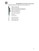
Отзывы: