FCU 500, FCU 505 · Edition 02.17
20
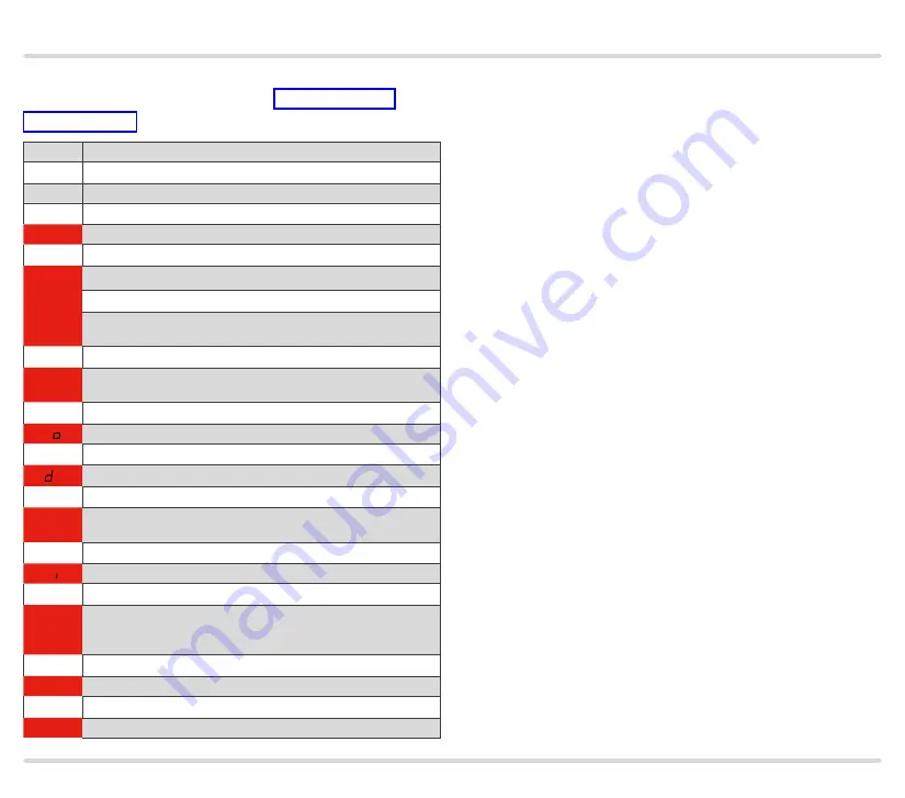
Function
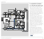
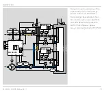
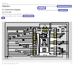
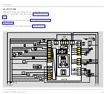
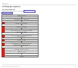
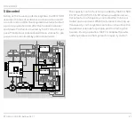
3 .2 .2 FCU 500 . .F1, FCU 500 . .F2
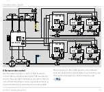
Example of application, see page 10 (Modulating
burner control)
Switch on the FCU
▼
In the event of fault signal: reset
▼
00
Start-up position/standby
▼
H0
Start-up with
ϑ
signal
▼
Switch-on delay time t
E
running (parameter 63)
Safety interlocks check
▼
01
Fan run-up time t
GV
running (parameter 30)
Pre-purge starts
▼
A
Actuator moves to the position for maximum capacity
▼
1
Air flow monitoring
▼
P1
Pre-purge time t
PV
running (parameter 34)
Tightness test (if equipped with TC)
▼
A
Actuator moves to the position for ignition capacity
▼
H7
Gas enable via valves V1 and V2
Enable signal to burner control units for the burner start via the
“safety interlock” output
▼
H8
Controller enabler signal delay time t
RF
running
▼
08
Operation/controller enable

