background image

KROHNE 

 Process instrumentation and measurement solutions

Flow

Level

Temperature

Pressure

Process Analysis

Services

Head Office KROHNE Messtechnik GmbH
Ludwig-Krohne-Str. 5
47058 Duisburg (Germany)
Tel.: +49 203 301 0
Fax: +49 203 301 10389
[email protected]

© KROHNE 06

/20

16 - 4

00499

9701 -

 MA

 WATERFLU

X 3070 -

 R0

1 en

 - Su

bj

ect

 to ch

an

ge with

ou

t n

oti

ce.

The current list of all KROHNE contacts and addresses can be found at:
www.krohne.com

Содержание WATERFLUX 3070

Страница 1: ...c water meter with optional KROHNE FlexPower Electronic Revision 5 0 2_ SW REV 5 0 2_ WATERFLUX 3070 WATERFLUX 3070 WATERFLUX 3070 WATERFLUX 3070 Handbook Handbook Handbook Handbook KROHNE 06 2016 4004999701 MA WATERFLUX 3070 R01 en ...

Страница 2: ...r any part thereof without the prior written authorisation of KROHNE Messtechnik GmbH Subject to change without notice 2 www krohne com 06 2016 4004999701 MA WATERFLUX 3070 R01 en Copyright 2016 by KROHNE Messtechnik GmbH Ludwig Krohne Str 5 47058 Duisburg Germany IMPRINT ...

Страница 3: ...stallation 15 3 1 General notes on installation 15 3 2 Storage 15 3 3 Transport 15 3 4 Pre installation requirements 16 3 5 General requirements 16 3 5 1 Vibration 16 3 5 2 Magnetic field 16 3 6 Installation conditions 17 3 6 1 Inlet and outlet 17 3 6 2 T section 17 3 6 3 Open feed or discharge 17 3 6 4 Bends 18 3 6 5 Pump 18 3 6 6 Control valve 19 3 6 7 Air venting and vacuum forces 19 3 6 8 Inst...

Страница 4: ... 2 Show software version diameter meter constant and display test on the display 40 6 1 3 Status information on the display 41 6 2 Access control 42 6 2 1 Access levels to the menu 42 6 2 2 Access to the service menu only 42 6 2 3 Meters subject to metrology 43 6 2 4 Metrological seals 43 6 2 5 Utility seals 44 6 2 6 Reset full access to the menu 45 6 3 Menu 46 6 3 1 View or change menu settings 4...

Страница 5: ...information 67 7 5 2 Form for copying to accompany a returned device 68 7 6 Disposal 68 8 Technical data 69 8 1 Measuring principle 69 8 2 Technical data 70 8 3 Integrated P T sensor optional 76 8 4 KROHNE FlexPower optional 77 8 5 Modbus protocol option 78 8 6 Legal metrology 79 8 6 1 OIML R49 79 8 6 2 MID Annex III MI 001 82 8 6 3 Verification to MID Annex III MI 001 and OIML R49 84 8 7 Measurem...

Страница 6: ...ards compatible changes and fault repair with no effect on operation e g spelling mistakes on display 3 _ Downwards compatible hardware and or software change of inputs and outputs P Pulse output S Status output X All inputs and outputs 4 Downwards compatible changes with new functions 5 Incompatible changes i e electronic equipment must be changed Release date Electronic revision Changes and comp...

Страница 7: ...ing Instruments Directive 2014 32 EU Annex III MI 001 For more information please refer to the dedicated documentation CAUTION Responsibility for the use of the measuring devices with regard to suitability intended use and corrosion resistance of the used materials against the measured fluid lies solely with the operator INFORMATION The manufacturer is not liable for any damage resulting from impr...

Страница 8: ... over the Internet e g when communicating by e mail may involve gaps in security It is not possible to protect such data completely against access by third parties We hereby expressly prohibit the use of the contact data published as part of our duty to publish an imprint for the purpose of sending us any advertising or informational materials that we have not expressly requested 1 4 2 Disclaimer ...

Страница 9: ...on To prevent any injury to the user or damage to the device it is essential that you read the information in this document and observe applicable national standards safety requirements and accident prevention regulations If this document is not in your native language and if you have any problems understanding the text we advise you to contact your local office for assistance The manufacturer can...

Страница 10: ...tial disregard of this warning can lead to serious health problems and even death There is also the risk of seriously damaging the device or parts of the operator s plant WARNING Disregarding this safety warning even if only in part poses the risk of serious health problems There is also the risk of damaging the device or parts of the operator s plant CAUTION Disregarding these instructions can re...

Страница 11: ...packs Do not weld or solder to the body of the battery Do not expose contents of battery to water Remove the battery from device before returning to the manufacturer for service or warranty reasons Dispose battery packs in accordance with local regulations where possible recycle used batteries WARNING Lithium batteries are primary power sources with high energy content If mistreated they may prese...

Страница 12: ...entation 3 Factory calibration report 4 CD ROM with product documentation in available languages 5 Combined signal power cable delivered according order 6 Sensor cable remote version 7 Wall holder remote version 8 Special wrench for loosening the locking ring of the cover 1 2 3 7 8 INFORMATION Assembly materials and tools are not part of the delivery Use the assembly materials and tools in complia...

Страница 13: ...er is mounted directly on the measuring sensor in polycarbonate IP68 housing Remote version measuring sensor with a stainless steelconnection box and a signal converter in a remote polycarbonate housing Both versions are available with an optional integrated P T sensor INFORMATION Product specific information and extensive product specification is available using PICK the Product Information Cente...

Страница 14: ...of nameplate 1 Name and address of the manufacturer 2 CE sign with number s of notified body bodies 3 Battery voltage UPS and Electronic Revision number 4 Optional MI 001 Additional information including approval number Q3 ratio 5 Meter constant diameter wetted materials protection class 6 Type designation of the flowmeter serial number date of manufacturing option text P T only for versions with ...

Страница 15: ... the signal converter housing Do not use lifting chains To transport flange devices use lifting straps Wrap these around both process connections INFORMATION Inspect the packaging carefully for damages or signs of rough handling Report damage to the carrier and to the local office of the manufacturer INFORMATION Do a check of the packing list to make sure that you have all the elements given in th...

Страница 16: ...rements 3 5 1 Vibration 3 5 2 Magnetic field INFORMATION The following precautions must be taken to ensure reliable installation Make sure that there is adequate space to the sides Protect the signal converter from direct sunlight and install a sun shade if necessary Signal converters installed in control cabinets require adequate cooling e g by fan or heat exchanger Do not expose the signal conve...

Страница 17: ...ed or discharge CAUTION To prevent damage to the Rilsan coating the WATERFLUX 3000 sensor must be installed carefully Take precautions during transport and installation to protect the in and outlet of the sensor Figure 3 4 Minimal inlet and outlet 1 Inlet 0 DN 2 Outlet 0 DN Figure 3 5 Distance behind a T section 1 0 DN Figure 3 6 Installation in front of an open discharge ...

Страница 18: ...4999701 MA WATERFLUX 3070 R01 en 3 6 4 Bends 3 6 5 Pump Figure 3 7 Installation in bending pipes Figure 3 8 Installation in bending pipes CAUTION Avoid draining or partial filling of the flow sensor Figure 3 9 Recommended installation behind a pump 1 Inlet 3 DN ...

Страница 19: ...om 06 2016 4004999701 MA WATERFLUX 3070 R01 en 3 6 6 Control valve 3 6 7 Air venting and vacuum forces Figure 3 10 Recommended installation in front of a control valve Figure 3 11 Air venting 1 5 m 2 Air ventilation point Figure 3 12 Vacuum 1 5 m ...

Страница 20: ...ted military plug and play connectors Submersion under water is possible down to a depth of 10 meters In applications with prolonged or continuous submersion it is advised to use the WATERFLUX 3070 remote version The remote IFC 070 signal converter and GPRS data logger unit can be installed on the wall of the measuring pit near the lid for visual read out of the display Note figures shows a cable ...

Страница 21: ...r aligned upwards or downwards Install flow sensor in line with the pipe axis Pipe flange faces must be parallel to each other Figure 3 15 Mounting position Figure 3 16 Flange deviation 1 Lmax 2 Lmin CAUTION Max permissible deviation of pipe flange faces Lmax Lmin 0 5 mm 0 02 CAUTION Use the proper tools to ensure the integrity of the meter and prevent damage to the Rilsan coating ...

Страница 22: ...theoretical and calculated for optimum conditions and use with carbon steel flanges Tightening of bolts Always tighten the bolts uniformly and in diagonally opposite sequence Do not exceed the maximum torque value Step 1 Apply approx 50 of max torque given in table Step 2 Apply approx 80 of max torque given in table Step 3 Apply 100 of max torque given in table Figure 3 17 Tightening of bolts ...

Страница 23: ...0 PN 10 8 x M 20 55 150 PN 16 8 x M 20 55 200 PN 10 8 x M 20 85 200 PN 16 12 x M 20 57 250 PN 10 12 x M 20 80 250 PN 16 12 x M 24 100 300 PN 10 12 x M 20 95 300 PN 16 12 x M 24 136 350 PN 10 16 x M 20 96 400 PN 10 16 x M 24 130 450 PN 10 20 x M 24 116 500 PN 10 20 x M 24 134 600 PN 10 20 x M 27 173 1 The torque values also depend on variables temperature bolt material gasket material lubricants et...

Страница 24: ...x 5 8 22 5 150 8 x 3 4 33 6 150 8 x 3 4 48 8 150 8 x 3 4 66 10 150 12 x 7 8 74 12 150 12 x 7 8 106 14 150 2 12 x 1 87 16 150 2 16 x 1 84 18 150 2 16 x 1 1 8 131 20 150 2 20 x 1 1 8 118 24 150 2 20 x 1 1 4 166 1 The torque values also depend on variables temperature bolt material gasket material lubricants etc outside the control of the manufacturer Therefore these values should be regarded as indi...

Страница 25: ...se the assembly materials and tools in compliance with the applicable occupational health and safety directives Figure 3 18 Mounting of the wall holder 1 Mark the fixation points 2 Drill the holes and mount the holder with the right screws eg M6 x 50 with washer and plugs Do not exceed a tightening torque of 2 Nm when fastening the screws This can damage the wall holder 3 Slide the IP68 remote ver...

Страница 26: ...g on the main power When attaching the wall holder unit to the wall do not exceed a tightening torque of 1 Nm when fastening the screws This can damage the mounting eyelets Mounting on the pipe line construction can easily be done by using 2 Tie Wraps The bottom of the housing of the KROHNE FlexPower unit is designed for mounting on a pipe line Choose the correct size and properties of the Tie Wra...

Страница 27: ...er Check for the correct supply voltage printed on the nameplate DANGER Electrical connection is carried out in conformity with the VDE 0100 directive Regulations for electrical power installations with line voltages up to 1000 V or equivalent national regulations CAUTION Use suitable cable entries for the various electrical cables The measuring sensor and signal converter have been configured tog...

Страница 28: ...CTIONS 28 WATERFLUX 3070 www krohne com 06 2016 4004999701 MA WATERFLUX 3070 R01 en 4 3 Grounding Figure 4 1 Grounding INFORMATION Grounding without grounding rings The flow sensor is equipped with a reference electrode ...

Страница 29: ...output passive maximum 3 outputs possible see status output 2x Pulse output passive maximum 3 outputs possible see status output f 100 Hz I 10 mA U 2 7 24 VDC P 100 mW Status output Status output Status output Status output 2x Status output passive 1 status output can be used as a third pulse output 2x Status output passive 1 status output can be used as a third pulse output 2x Status output passi...

Страница 30: ...eads leads Standard sensor cable Sensor cable with integrated P T option Wire color Terminal Function Brown 1 Reference electrode White 2 Standard electrode signal Violet 3 Standard electrode signal Blue 7 Field current Green 8 Field current Yellow 9 No function Drain wires Screws Shielding INFORMATION The standard WSC2 sensor cable double shielded includes both electrode and field current leads a...

Страница 31: ...tions next chapter Figure 4 2 Output cable at IP68 compact version 1 Color coded leads of the output cable Wire color Contact on connector Function Yellow A Status output 1 or threshold for P or T or pulse output C White G Status output 2 or threshold for P or T Blue H Ground Brown B Pulse output A Green F Pulse output B Pink C External battery Grey E External battery Note with or without shieldin...

Страница 32: ...cable Modbus cable Figure 4 3 Different output cable IP68 remote version 1 Color coded leads of sensor cable 2 Y cable with additional power cable 3 I O cable pulse modbus 4 I O connection 5 RVS sensor cable connection Wire color Contact on connector Function Yellow A Status output 1 or threshold for P or T or pulse output C White G Status output 2 or threshold for P or T Blue H Ground Brown B Pul...

Страница 33: ...r pulse output C White G Status output 2 or threshold for P or T Grey H Ground Brown B Pulse output A Green F Pulse output B Brown C External power 3 6V White E External power Ground Shield D Shielding Wire color Contact on connector Function Shield C Shielding Brown B White A Ground Green E Down link wire A Yellow K Down link wire B Pink H Up link wire A Grey J Up link wire B Brown F External pow...

Страница 34: ...n on the different battery types refer to Types of batteries on page 63 CAUTION Please connect the battery before first use The signal converter is delivered with a disconnected battery INFORMATION For transport purposes signal converters which are verified to MI 001 or OIML R49 have also disconnected batteries Please connect battery before placing the local utility seal Figure 5 1 Connecting the ...

Страница 35: ...ply More information regarding the exchange replacing of battery refer to Types of batteries on page 63 or refer to Battery lifetime on page 90 for typical lifetimes of batteries 5 4 Power supply KROHNE FlexPower Beside regular battery power supplies the WATERFLUX 3070 can also be connected to an external KROHNE FlexPower unit The external KROHNE FlexPower unit has an internal Lithium battery pack...

Страница 36: ... converter active the power source is AC DC If both are not available interrupted the internal dual D cell battery pack 3 6V 38 Ah automatically takes over the power supply To save energy the WATERFLUX 3070 will automatically switch to the low power consuming battery backup mode and will continue to totalize volumes but temporarily stop to transfer the data The FlexPower unit is IP68 rated and tot...

Страница 37: ...le grey cable grey cable grey cable Cable Ø 0 75 mm2 5 5 Starting the signal converter The measuring device consist of a sensor and a converter and is ready for operation When the power is switched on battery or FlexPower unit is connected a self test is carried out and after that the meter starts to operate Wire color Connection Red DC Blue DC Yellow Green FE functional earth Wire color Connectio...

Страница 38: ... used to cycle the display and to access the menu Figure 6 1 Display and operating elements 1 Counter value or flow rate 2 Status information including battery status flow direction and counter settings 3 Optical keys and to navigate the menu and for display options 4 Reset button only accessible after removing the housing Optional P T sensor 1 Display showing temperature value 2 Display showing p...

Страница 39: ...r 1 second to cycle to the next display Leave the optical key untouched to keep the current display If the meter is set to AMR mode the display will always switch back to the sum counter display Display symbols for flow direction and counter settings Display Description Menu setting Sum counter default Always available Forward counter Available if menu number 13 is set to 1 Reverse counter Availab...

Страница 40: ...untouched at any time to return to the main display Display Description Example Example Example Example of the instrument serial number Example Example Example Example of the software version CrC cyclic redundancy check integrity test of the memory and software Example Example Example Example CrC CAF5 is SWR 4 3 0_ Example of the diameter 125 and the meter constant 4 160 Example Example Example Ex...

Страница 41: ...rly empty Replace the battery Battery empty voltage too low Flashing Warning Check all connections If the exclamation mark does not disappear contact the service department X 1 127 Impaired software integrity The meter has stored the last counter values and went to sleep mode Contact the service department Empty pipe Available if menu number 83 is set to 1 When the pressure temperature is above or...

Страница 42: ...ecomes available after placing a jumper inside the converter housing The service menu gives no access to items that are subject to legal metrology For an overview of menu items available in the service menu refer to Menu overview on page 47 Access levels to the menu Menu settings Full menu access Menu number 1 is set to 0 Access to the service menu only Menu number 1 is set to 1 Use a jumper to ga...

Страница 43: ...er Parameters subject to fiscal metering are not available via the service menu The software version diameter and meter constant are fiscal parameters These values can be read on the display and checked with the values on the name plate without breaking the sealing For more information please refer to Show software version diameter meter constant and display test on the display on page 40 6 2 4 Me...

Страница 44: ...owing figures provide an example for additional utility seals A utility seal on the outer housing of the converter and a utility seal on the measurement sensor can provide evidence of an intervention by an non authorised person Figure 6 3 Examples of a utility seal with the remote version 1 Location of seals Figure 6 4 Example of a utility seal Figure 6 5 Utility seal on snap on plug connection 1 ...

Страница 45: ...umber 1 To change the setting of menu number 1 from 1 to 0 please refer to View or change menu settings on page 46 For closing the case of the converter in the IP68 housing please refer to Closing of the converter housing on page 25 WARNING Do not break the metrological seals if the meter has been verified to MID Annex III MI 001 or OIML R49 and has received metrological sealing This can lead to t...

Страница 46: ...ure when the meter is verified to MID Annex III MI 001 or OIML R49 Function Keys Display To start the programming mode Hold the and the key for 5 seconds The display flashes To enter the menu Press the key within 3 seconds Left menu number Right menu setting To navigate through the menu to the required menu number Press the key To change the menu setting Press the key The menu setting starts to fl...

Страница 47: ... flow rate Counters and flow rate Counters and flow rate 10 Counter unit of volume 01 m3 11 Counter number of decimals 99 Automatically 12 Counter multiplier value 99 Automatically 13 Show forward counter 0 Off 14 Show reverse counter 0 Off 15 Flow rate unit of volume time 0102 m3 h 16 Flow rate unit of time 99 Automatically 17 Show flow rate 0 Off Pulse output Pulse output Pulse output Pulse outp...

Страница 48: ...mperature optional 60 Pressure sensor 0 Off 61 Pressure unit 00 bar 1 decimal 62 Pressure limit Maximum xx x 16 0 bar 63 Pressure limit Minimum 0 5 bar 64 Show pressure 0 Off 65 Temperature sensor 0 Off 66 Temperature unit 00 C 67 Temperature limit Maximum xxx 70 C 68 Temperature limit Minimum xxx 5 C 69 Show temperature 0 Off 70 P T measuring rate 15 15 minutes Measurement settings Measurement se...

Страница 49: ...tion at power failure 0 Off Modbus RS485 Modbus RS485 Modbus RS485 Modbus RS485 C0 Modbus slave adress 001 Value to be programmed 1 to 247 C1 Baud rate 9 6 9600 baud C2 Parity rate 0 Even C3 Register format 1 Big endian C4 Transmission delay 50 50 ms C5 Stop bits 1 1 Stop bit C6 User application name 00000 To be set C7 RS485 bus termination 0 No RS485 termination C8 Reception interval 0 Set 0 3600...

Страница 50: ...play a higher accuracy with a decimal dot menu number 11 The multiplier value enables the display of volumes with more than 8 digits menu number 12 If a multiplier is selected the multiplier value is shown in the top right corner of the display The value on the display must be multiplied with a factor 10 100 or 1000 to get the actual counter value The decimal dot and multiplier value are not avail...

Страница 51: ...value 99 Automatically default Shows counter value divided by the multiplier value entered 99 The multiplier value is set automatically 1 x 1 10 x 10 100 x 100 1000 x 1000 13 Show forward counter 0 Off default Makes the item available on the display 1 On 14 Show reverse counter 0 Off default Makes the item available on the display 1 On 15 Flow rate unit of volume time 0000 Litre per second l s 000...

Страница 52: ...e flow pulse output A runs behind pulse output B If after a phase shift 90 pulse output A runs behind pulse output B the number of pulses need to be subtracted from the total to get the net volume equal to the sum counter on the display Pulse output A gives the forward volume and pulse output B gives the reverse volume passing through the meter For a net volume equal to the sum counter on the disp...

Страница 53: ...ault Pulse output B 1 On 22 Pulse output A and B phase shift 0 90 offset default Sets the relation between pulse output A and B Menu no 20 and 21 must be set to 1 on 1 Forward reverse 2 Net forward volume 23 Pulse output A and B pulse width 5 5 ms default The pulse width is always the same for pulse output A and B A small pulse width means a lower energy consumption of the battery 10 10 ms 20 20 m...

Страница 54: ...battery 10 10 ms 20 20 ms 50 50 ms 100 100 ms 200 200 ms 33 Pulse output C pulse value 00100 litre Value to set in unit of volume per pulse Unit and format are determined by setting menu item 31 00 100 default m3 pulse 0010 0 gallon 0010 0 imp gallon 001 00 ft 3 00100 a inch 00100 a ft 0 1000 m3 pulse When menu item A2 is set on 1 No Function Options Description No Function Options Description 40 ...

Страница 55: ...case of low battery remaining capacity 10 1 On 52 Status output 2 Battery final warning 0 Off default Active in case of very low battery remaining capacity 1 1 On 53 Status output 2 Empty pipe 0 Off default Active in case of empty pipe detection 1 On 54 Status output 2 P T warning 0 default Off 1 Pressure limit max menu item 62 2 Pressure limit min menu item 63 3 Temperature limit max menu item 67...

Страница 56: ...8 Tmax limit menu number 44 setting 3 Tmin limit menu number 54 setting 4 Once the measured temperature reaches Tmax 25 C the status output 1 gives an alarm and sends out pulses When the measured temperature decreases and reach Tmin 7 C the status output 2 gives an alarm similar to status output 1 When the temperature stays within Tmax Tmin limit settings 7 25 C no alarm will be set See the illust...

Страница 57: ...0 mbar xxxxx 07 Range 7 232 psi xxx 64 Show pressure 0 Off default Not visible in display 1 On Visible in display 65 Temperature sensor 0 Off default Disabled 1 On Enabled 66 Temperature unit 00 default C 01 F 67 Temperature limit maximum 070 Range 0 70 C xxx 158 Range 23 158 F xxx 68 Temperature limit minimum 05 Range 5 70 C xxx 23 Range 23 158 F xxx 69 Show temperature 0 Off Not visible in displ...

Страница 58: ... 5 5 sec Sets the interval time between two measurements The default value of 15 sec is chosen for an optimal energy consumption of the battery 10 10 sec 15 15 sec default 20 20 sec 82 Low flow cut off 0 0 mm s Low flow cut off in mm s Measurements below this value are neglected 5 5 mm s 10 10 mm s default 83 Empty pipe detection EP 0 Off default If switched to 1 on the display shows EP in case of...

Страница 59: ...sed on setting menu item 1 93 Zero offset calibration 0 Off default After a countdown the meter automatically switches back to the measuring mode and to the main display The setting goes back to zero Menu number 94 is automatically set to 1 1 In situ determination of zero point 94 Zero selection 0 Factory setting default Factory setting based on factory calibration 1 Measured value The measured va...

Страница 60: ...he reset 00000 Reset A2 Verification mode 0 Off The display indicates Pxxxxxxx the decimal separator position varies per diameter Please refer to Verification mode on page 62 for more details 1 On A3 Add on communication 0 Off Factory setting 1 On No Function Options Description B0 Battery type 0 No battery A wrong setting influences the battery lifetime calculation 2 Two internal batteries 3 Exte...

Страница 61: ...600 baud 4 8 4800 baud 9 6 9600 baud default 19 2 19200 baud 38 4 38400 baud 57 6 57600 baud 115 2 115200 baud C2 Parity rate 0 Even default 1 Odd 2 No parity C3 Register format 0 Little endian 1 Big endian default 2 Mix endian small words 3 Mix endian large words C4 Transmission delay 0 0ms Transmission delay can be set by choice from table 5 5ms 10 10ms 20 20ms 30 30ms 40 40ms 50 50ms default C5...

Страница 62: ... set to m3 To go back to the standard mode menu number A2 should be set to 0 6 4 3 Test mode A test mode is available with which a second sum counter is activated The second sum counter can be activated without breaking the metrological seals Activating the second sum counter has no effect on the measurement and does not affect the counter values The second sum counter starts counting from 0 The r...

Страница 63: ...ailable They can be exchanged by one of the other types Standard the IFC 070 signal converter is deliverd with a lithium dual D cell 3 6V 38 Ah Optionally an external battery pack with a lithium dual DD cell 3 6V 70 Ah can be connected Figure 7 1 Batteries and battery holders 1 Internal dual D cell battery without in holder 2 External dual DD cell KROHNE PowerBlock ...

Страница 64: ... holder Replace the holder Fasten the battery connector to the internal connector in the converter Check if the display lights up Put back the cover and locking ring For closing the case of the signal converter in the IP68 housing refer to Closing of the converter housing on page 25 Figure 7 2 Removing the battery holder WARNING Make sure that the battery cable is not jammed by the cover INFORMATI...

Страница 65: ...ch Remove the cover Disconnect the connector of the battery Remove the old battery Fasten the battery connector to the internal connector in the converter Connect the external battery by the power connection cable and or battery connection cable Check if the display lights up Put back the cover and lock refer to Closing of the converter housing on page 25 Figure 7 3 Connecting the external battery...

Страница 66: ...E FlexPower results in a 4 2 V DC output When a main power failure occurs the internal dual D cell battery will take over the power supply to the IFC 070 signal converter as back up with a voltage of 3 6 V DC More information about battery lifetime can be found in refer to Battery lifetime on page 90 The input power for the KROHNE FlexPower can be realized by connecting an AC mains supply source r...

Страница 67: ...nstructions it will rarely present any problems INFORMATION For more precise information please contact your local sales office CAUTION Should you nevertheless need to return a device for inspection or repair please pay strict attention to the following points Due to statutory regulations on environmental protection and safeguarding the health and safety of the personnel the manufacturer may only ...

Страница 68: ...ice when it is returned Date Signature Stamp CAUTION Disposal must be carried out in accordance with legislation applicable in your country Separate collection of WEEE Waste Electrical and Electronic Equipment in the European Union Separate collection of WEEE Waste Electrical and Electronic Equipment in the European Union Separate collection of WEEE Waste Electrical and Electronic Equipment in the...

Страница 69: ...thus the flow rate Q A signal converter is used to amplify the signal voltage filter it and convert it into signals for totalizing recording and output processing Rectangular cross section Rectangular cross section Rectangular cross section Rectangular cross section The minimal height of the measuring tube decreases the distance between the field coils 1 resulting in a stronger and more homogeneou...

Страница 70: ...or restricted to DN50 200 refer to Integrated P T sensor optional on page 76 Self providing energy by batteries for up to 10 years Modular construction The measurement system consists of a flow sensor and a signal converter It is available as a compact and as a remote version Compact version With IFC 070 converter WATERFLUX 3070 C Remote version In field F version with IFC 070 converter WATERFLUX ...

Страница 71: ...mm s DN350 600 down to 0 4 of the measured value 1 mm s The maximum measuring error depends on the installation conditions For detailed information refer to Measurement accuracy on page 85 Repeatability DN 25 300 0 1 v 0 5 m s 1 5 ft s DN350 600 0 2 v 0 5 m s 1 5 ft s Calibration Verification Standard Standard Standard Standard 2 Point calibration by a direct volume comparison Optional Optional Op...

Страница 72: ... C 23 158 F Ambient temperature 25 65 C 13 149 F Ambient temperatures below 25 C 13 F may affect the readability of the display It is recommended to protect the converter from external heat sources such as direct sunlight because high temperatures reduce the life cycle of all electronic components and the battery Storage temperature 30 70 C 22 158 F Measurement range Measurement range Measurement ...

Страница 73: ...s Sensor housing Sheet steel Measuring tube DN25 200 metallic alloy DN250 600 stainless steel Flanges DN25 150 Stainless Steel 1 4404 316L DN200 Stainless Steel 1 4301 304L DN250 DN600 Steel St37 C22 A105 Optional DN250 DN600 Stainless Steel Liner Rilsan Protective coating On exterior of the meter flanges housing and or connection box field version Standard coating Option subsoil coating Measuring...

Страница 74: ...FC 070 C and F IFC 070 C and F Connection with 1 or 2 snap on connectors Output cable IFC 070 C and F IFC 070 C and F IFC 070 C and F IFC 070 C and F Standard Pulse or Modbus output cable Optional Pulse output activated and connection to KGA 42 data logger GPRS module Output cable with 2 plug and play IP68 rated connectors Power supply Power supply Power supply Power supply Battery Standard Standa...

Страница 75: ...bus Approvals and certificates CE CE CE CE This device fulfils the statutory requirements of the EU directives The manufacturer certifies successful testing of the product by applying the CE mark For full information of the EU directives standards and the approved certifications please refer to the CE declaration or the manufacturer website Custody transfer Not valid for integrated temperature and...

Страница 76: ...00 Measurements Measuring range Pressure 0 5 16 bar 7 3 232 psi relative Temperature 5 70 C 23 158 F Measuring units Pressure Default setting bar Selectable mbar psi Temperature Default setting C Selectable F Measurement interval Default setting 15 min Selectable 1m 5m 10m 15m or equal to the measurement flow interval Measuring accuracy Maximum measuring accuracy Pressure 1 of full scale 0 5 16 ba...

Страница 77: ...mbined power and output Y cable with snap on connector Power Cable DC cable green and AC cable grey Temperature Storage and transport temperature 30 70 C 22 158 F Maximum operating temperature 25 C 65 C 13 149 F Approval Transport Certificate under UN38 3 requirements Transportation Tests for Lithium batteries Other approval and standards Other approval and standards Other approval and standards O...

Страница 78: ...have the same baud rate and settings but different unique addresses General technical data CAUTION Please note that changing the baud rate will greatly affect the units battery life time The baud rate equal to and below 9600 bps are considered energy efficient while baud rates greater than 9600 bps are not Baud rate 1200 2400 3600 4800 9600 default 19200 38400 57600 or 115200 Protocol Modbus RTU d...

Страница 79: ... R ratio The WATERFLUX 3070 meets the requirements for water meters of accuracy class 1 and 2 For accuracy class 1 the maximum permissible error for water meters is 1 for the upper flow rate zone and 3 for the lower flow rate zones For accuracy class 2 the maximum permissible error for water meters is 2 for the upper flow rate zone and 5 for the lower flow rate zones According to OIML R49 accuracy...

Страница 80: ...sitional Q2 Permanent Q3 Overload Q4 65 250 0 400 0 64 100 125 80 250 0 640 1 02 160 200 100 250 1 00 1 60 250 312 5 125 250 1 60 2 56 400 500 150 250 2 52 4 03 630 787 5 200 160 3 9375 6 30 630 787 5 250 160 6 25 10 00 1000 1250 300 160 10 00 16 00 1600 2000 350 160 15 625 25 00 2500 3125 400 160 25 40 00 4000 5000 450 160 25 40 00 4000 5000 500 160 39 375 63 00 6300 7875 600 100 63 100 80 6300 7...

Страница 81: ...60 40 50 0 50 400 0 1575 0 252 63 78 75 65 400 0 1575 0 25 63 78 75 65 400 0 250 0 40 100 125 0 80 400 0 250 0 40 100 125 0 80 400 0 400 0 64 160 200 0 100 400 0 400 0 64 160 200 0 100 400 0 625 1 00 250 312 5 125 400 0 625 1 00 250 312 5 125 400 1 000 1 60 400 500 0 150 400 1 000 1 60 400 500 0 150 400 1 575 2 52 630 787 5 200 400 1 575 2 52 630 787 5 250 400 2 500 4 00 1000 1250 300 400 4 000 6 ...

Страница 82: ...X 3070 has an EC type examination certificate and can be verified to the MID Annex III MI 001 for water meters with diameter DN25 DN600 The conformity assessment procedure followed for WATERFLUX 3070 is Module B Type Examination and Module D Quality Assurance of the Production Process The maximim permissible error on volumes delivered between Q2 transitional flow rate and Q4 overload flow rate is ...

Страница 83: ... 20 0 40 640 0 0625 0 100 40 50 0 50 630 0 100 0 160 63 78 75 65 635 0 1575 0 252 100 125 0 80 640 0 25 0 400 160 200 0 100 625 0 40 0 640 250 312 5 125 640 0 625 1 00 400 500 0 150 630 1 00 1 60 630 787 5 200 508 1 575 2 52 800 1000 250 400 2 50 4 00 1000 1250 300 400 4 00 6 40 1600 2000 350 160 15 625 25 0 2500 3125 400 160 25 00 40 0 4000 5000 450 160 25 00 40 0 4000 5000 500 160 39 375 63 0 63...

Страница 84: ... for R Q1 Q2 and Q3 Verification to OIML R49 class 1 and at other values for R and Q3 available on request DN Span R Flow rate m3 h Q1 Q2 Q3 25 80 0 050 0 08 4 40 80 0 125 0 20 10 50 80 0 200 0 32 16 65 80 0 313 0 50 25 80 80 0 500 0 80 40 100 80 0 788 1 26 63 125 80 1 250 2 00 100 150 80 2 000 3 20 160 200 80 3 125 5 00 250 250 80 5 000 8 00 400 300 80 7 875 12 60 630 350 80 20 00 32 0 1600 400 8...

Страница 85: ...the water meter is defined and documented in an individual water meter calibration certificate Reference conditions Medium water Temperature 10 30 C 50 86 F Pressure 1 bar 14 5 psi Inlet section 3 DN Outlet section 1 DN Accuracy with signal converter IFC 070 Figure 8 4 Measuring accuracy X m s Flow velocity Y Maximum measuring error Inlet Outlet Accuracy Curve DN25 300 1 12 3 DN 1 DN 0 2 1 mm s 1 ...

Страница 86: ...flow velocity and flow profile are optimized within the rectangular and reduced cross section the additional uncertainty for upstream disturbances are drastically reduced Therefore the requirements for straight length and in front of and behind a meter are reduced The NMi has performed tests with various flow and swirl disturbers according to ISO 4064 and EN 14154 Based on these results the WATERF...

Страница 87: ... 161 mm 6 3 b 177 mm 7 Compact version in Compact version in Compact version in Compact version in polycarbonatehousing polycarbonatehousing polycarbonatehousing polycarbonatehousing IP68 IP68 IP68 IP68 a 159 mm 6 3 b 161 mm 6 3 Total height H a 1 The value may vary depending on the used cable glands INFORMATION All data given in the following tables are based on standard versions of the flow sens...

Страница 88: ...9 200 350 361 340 36 250 400 408 395 50 300 500 458 445 60 350 500 510 505 85 400 600 568 565 110 450 600 618 615 125 500 600 671 670 120 600 600 781 780 180 Nominal size inches Dimensions inches Approx weight lb L H W 1 5 91 5 83 4 3 18 1 5 91 6 4 9 21 2 7 87 7 05 5 9 34 3 7 87 8 03 7 5 42 4 9 84 9 49 9 0 56 5 9 84 10 55 10 0 65 6 11 81 11 69 11 0 80 8 13 78 14 25 13 5 100 10 15 75 16 3 16 0 148 ...

Страница 89: ...UX 3070 R01 en 8 9 Pressure loss Figure 8 5 Pressure loss between 1 m s and 9 m s for DN25 150 1 DN25 2 DN40 3 DN50 4 DN65 5 DN80 6 DN100 7 DN125 8 DN150 Figure 8 6 Pressure loss between 1 m s and 9 m s for DN200 600 1 DN200 2 DN250 3 DN300 4 DN350 5 DN400 6 DN450 7 DN500 8 DN600 ...

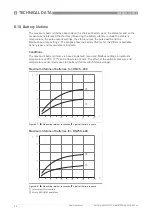
Страница 90: ...time for the different available battery types and measurement intervals Conditions The maximum battery lifetime is based on default menu and Modbus settings an ambient temperature of 25 C 77 F and a flow rate at 2 m s The effect of the optional pressure and temperature sensor decreases the battery lifetime with 5 on average Maximum lifetime of batteries for DN25 200 Figure 8 7 X X X X Measuring i...

Страница 91: ...NOTES 9 91 WATERFLUX 3070 www krohne com 06 2016 4004999701 MA WATERFLUX 3070 R01 en ...

Страница 92: ...ervices Head Office KROHNE Messtechnik GmbH Ludwig Krohne Str 5 47058 Duisburg Germany Tel 49 203 301 0 Fax 49 203 301 10389 info krohne com KROHNE 06 2016 4004999701 MA WATERFLUX 3070 R01 en Subject to change without notice The current list of all KROHNE contacts and addresses can be found at www krohne com ...

Отзывы: