KROHNE OPTISYS TUR 1060 Скачать руководство пользователя страница 52

5

 OPERATION 

52 

OPTISYS TUR 1060

www.krohne.com

01/2019 - 4007152501 - MA OPTISYS TUR 1060 R01 en
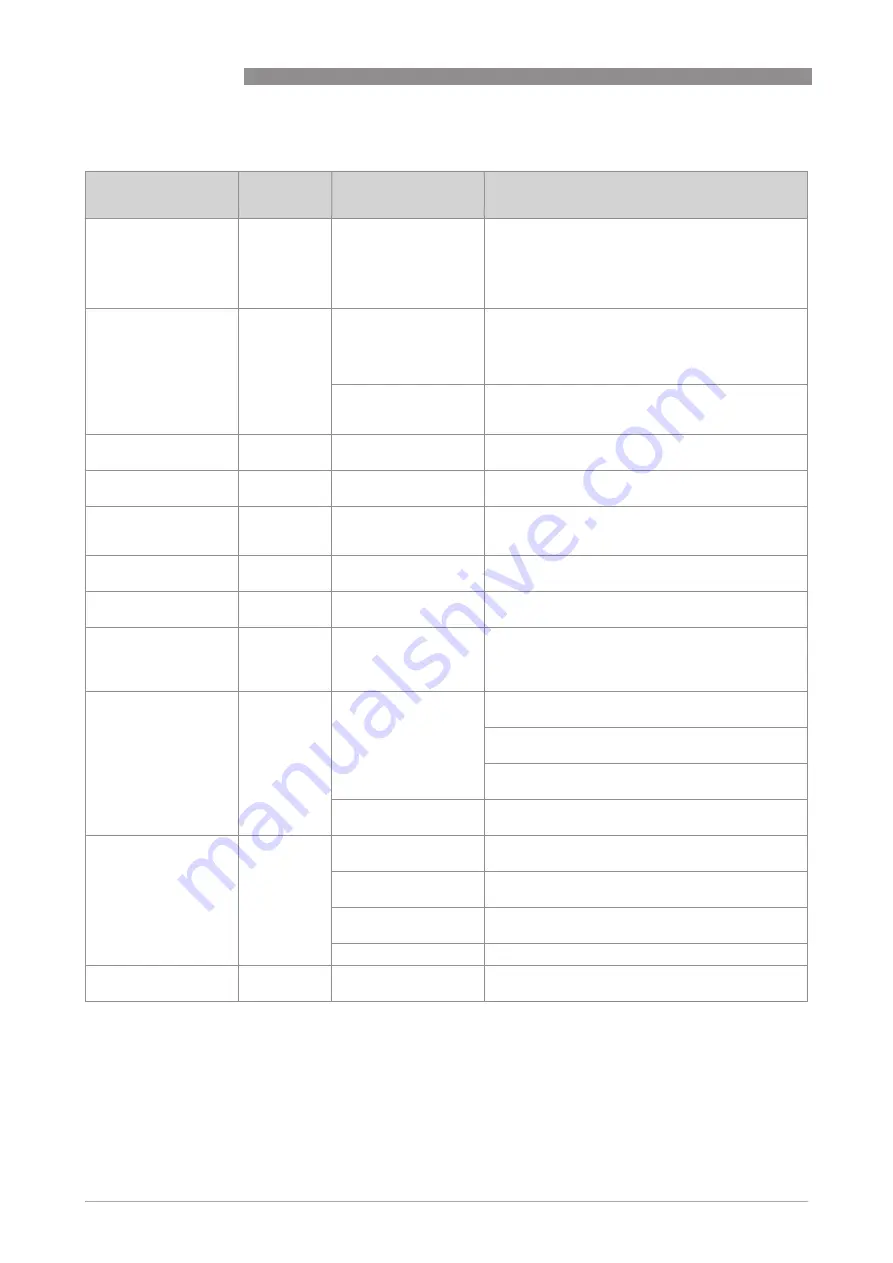
Fault chart

Fault message / 
problem

Category

Cause

Measurement

CAL

CAL

CAL

CAL (bottom row of 

display)

Error

Deficient calibration or 

calibration impossible.

Ensure that you use a proper calibration liquid (the 

best way is to use the calibration cuvettes of the 

manufacturer); if the calibration fails nonetheless, 

check the output of the sensor lamp and clean it or 

replace. After you remedied the problem, you have 

to recalibrate the device.

CLN

CLN

CLN

CLN (bottom row of 

display)

Error

Ultrasonic transducer 

has no contact to the 

spring connections or 

transducer itself is 

damaged.

Rotate ultrasonic cuvette slightly to improve the 

spring connection; if message persists, the 

transducer itself is damaged and you have to 

replace the whole cuvette.

Ultrasonic cuvette has 

been removed or 

wrong cuvette is used.

Insert correct ultrasonic cuvette and pay attention 

to the correct procedure (details on page 20).

DESC

DESC

DESC

DESC (bottom row of 

display)

Warning

Desiccant in the pouch 

is saturated or bad.

Change desiccant pouch (details on page 54).

FAIL

FAIL

FAIL

FAIL (bottom row of 

display)

Failure

Complete malfunction 

of an internal system.

Return the device to the manufacturer.

FLOW

FLOW

FLOW

FLOW (bottom row of 

display, only if flow 

switch is installed)

Error

Sample flow stopped.

Restore sample flow, contact manufacturer for 

further information.

LAMP

LAMP

LAMP

LAMP (bottom row of 

display)

Error

Light source fails.

A service employee of the manufacturer has to 

replace the lamp, do not do it on your own!

MA

MA

MA

MA (bottom row of 

display)

Error

4...20 mA loop open.

Check wiring of the current output (details on page 

25).

Measuring result 

blinks (i.e. value in the 

upper row of the 

display)

-

Exceeding of 

measuring range, i.e. 

turbidity is too high.

Take a sample and check the turbidity in a 

laboratory.

Measuring result 

alternates extremely

-

Bubbles in the 

measured medium.

Ensure that the drain vent hole is open and not 

blocked.

Apply backpressure with the help of the 

backpressure valve.

In case of severe bubble formation use a bubble 

trap (available as accessory part).

Debris in the ultrasonic 

cuvette.

Remove cuvette (details on page 53) and clean it 

with a soft cloth.

Measuring result is 

higher than expected

-

Bubbles in the 

measured medium.

See above in this table.

Condensate or dirt in 

the ultrasonic cuvette

Remove cuvette (details on page 53) and clean it 

with a soft cloth.

Leaky ultrasonic 

cuvette.

Check for leakages and replace devices if 

necessary.

Improper calibration.

Recalibrate the device (details on page 35).

Measuring result is 

lower than expected

-

Improper calibration.

Recalibrate the device (details on page 35).

Содержание OPTISYS TUR 1060

Страница 1: ...Compact measuring system for turbidity OPTISYS TUR 1060 OPTISYS TUR 1060 OPTISYS TUR 1060 OPTISYS TUR 1060 Handbook Handbook Handbook Handbook KROHNE 01 2019 4007152501 MA OPTISYS TUR 1060 R01 en...

Страница 2: ...any part thereof without the prior written authorisation of KROHNE Messtechnik GmbH Subject to change without notice 2 www krohne com 01 2019 4007152501 MA OPTISYS TUR 1060 R01 en Copyright 2019 by KR...

Страница 3: ...stallation 14 3 2 Storage and transport 14 3 3 Requirements of the device 14 3 4 Installation order 15 3 4 1 Placing the desiccant pouch and the humidity indicator 15 3 4 2 Selecting site and mounting...

Страница 4: ...response Signal Averaging 44 5 9 7 Resolution of the measured value 44 5 9 8 Display backlight brightness 45 5 9 9 Setting the units 45 5 9 10 Ultrasonic cleaning 46 5 9 11 RS 485 parameters Modbus 4...

Страница 5: ...CONTENTS 5 www krohne com 01 2019 4007152501 MA OPTISYS TUR 1060 R01 en OPTISYS TUR 1060 7 2 Technical data table 59 7 3 Dimensions and weight 61 8 Notes 62...

Страница 6: ...rd and immunity for industrial environments Low Voltage Directive Safety requirements for electrical equipment for measurement control and laboratory use in accordance with EN 61010 1 2010 Edition 2 0...

Страница 7: ...n over the Internet e g when communicating by e mail may involve gaps in security It is not possible to protect such data completely against access by third parties We hereby expressly prohibit the us...

Страница 8: ...ion To prevent any injury to the user or damage to the device it is essential that you read the information in this document and observe applicable national standards safety requirements and accident...

Страница 9: ...warnings must be observed without fail Even partial disregard of this warning can lead to serious health problems and even death There is also the risk of seriously damaging the device or parts of th...

Страница 10: ...sure that the device is delivered according to your order Check for the correct supply voltage printed on the nameplate INFORMATION Assembly materials and tools are not part of the delivery Use the as...

Страница 11: ...3 Drain tubing 4 Backpressure valve allows adjustment of the amount of back pressure which helps to control the flow rate and elim inate small bubbles 5 Display LCD 6 Operation keys 7 Drain hose conne...

Страница 12: ...he air a fan inside the device continuously circulates this heated and by the desiccant pouch dehumidified air around the optical well and the electronic device This features eliminates the need for a...

Страница 13: ...equency through spring connections in the upper part of the device to a piezo transducer at the bottom of the ultrasonic cuvette The ultrasonic cleaning can increase the time between cleanings signifi...

Страница 14: ...5 psi built in regulator set at 1 bar 15 psi Maximum allowable flow rate of the cuvette 0 1 1 5 l min 0 026 0 4 gal min Maximum fluid temperature 50 C 122 F INFORMATION Inspect the packaging carefully...

Страница 15: ...per part of the device after removing you can discard the tube CAUTION Installation assembly start up and maintenance may only be performed by appropriately trained personnel The regional occupational...

Страница 16: ...ecting it 3 4 2 Selecting site and mounting The preferred way of mounting of the device is wall mounting If this is not possible you can mount the device on any suitable level surface Irrespective of...

Страница 17: ...ox power assembly at first Put the electronic device on top of the junction box power assembly and use screws M6 1 4 to fix it 3 4 3 Mounting dimensions INFORMATION The design of the device recommends...

Страница 18: ...elivery For this purpose use hoses with the following specifications 1 4 inch OD flexible tubing Opaque hose material to prevent algae growth if direct sunlight can reach the hose CAUTION Do not conne...

Страница 19: ...it is secured 3 4 6 Drain vent Select a hose diameter of 1 4 inches OD polyethylene or polypropylene Make sure that the hose is long enough to connect the drain directly to a suitable location Ensure...

Страница 20: ...the cuvette with a soft cloth just before inserting it The dehumidification system cannot remove large droplets of water only residual moisture Figure 3 4 Procedure for inserting and fixing the ultra...

Страница 21: ...e DANGER Observe the national regulations for electrical installations WARNING Observe without fail the local occupational health and safety regulations Any work done on the electrical components of t...

Страница 22: ...de energise all cables before starting any installation or service work otherwise a perilous electric shock can happen CAUTION The device has a switching power supply which demands 100 240 VAC and 47...

Страница 23: ...ER The device involves a line voltage that could endanger life Only qualified electricians are allowed to perform the electrical installation of the device Always note all local and government recomme...

Страница 24: ...nnections are on the upper row The RS 485 and 4 20mA are on the lower row These connections are rated for a wire size from 12 30 AWG 0 05 3 mm2 either solid or stranded The terminals ALARM 1 and ALARM...

Страница 25: ...e operates with differential levels that are unsusceptible to electrical interferences This is why the usage of cable lengths up to 900 m 2950 ft is possible Independent of the output mode analog or d...

Страница 26: ...ing the sensor interconnect cable CAUTION Always connect the sensor interconnect cable with the upper part of the device last of all The reason is that if you connect the sensor interconnect cable bef...

Страница 27: ...start up and typically 45 minutes during all following start ups at the same time the fully automatic drying process takes place i After the warm up the display shows the measured turbidity if a conti...

Страница 28: ...multaneously the lower row displays the current scale and the upper row the measured reading The following drawing is an example for a display during normal operation Figure 5 1 Description of the dis...

Страница 29: ...Using or to select each digit The flashing digit is the number that is currently being adjusted Press to move on to the next digit If the code is adjusted press to switch to the next item in the menu...

Страница 30: ...pt the first number of the code i Now the second number of the code is flashing Repeat the previous step with the second number confirm the chosen number with the button Repeat the previous step with...

Страница 31: ...pecifications Configuration CONFIG Configuration CONFIG Configuration CONFIG Configuration CONFIG mode for customer specific adjustments and preferred operation at any time during normal operation The...

Страница 32: ...onally as they contain further information Main menu Submenu Parameter AUTO AUTO AUTO AUTO Automatic Automatic Automatic Automatic Operation Operation Operation Operation This mode is the normal autom...

Страница 33: ...LV ERLV ERLV Error Level 0 00 2 00 4 00 OFF BAUD BAUD BAUD BAUD Baud Rate 2400 4800 9600 19200 ADDR ADDR ADDR ADDR Modbus Address 1 255 ALM1 ALM1 ALM1 ALM1 Alarm 1 OFF HI LO Error S P Setpoint DLY Del...

Страница 34: ...UNIT Display Units ntu Fnu CLN CLN CLN CLN Ultrasonic Cleaning On OFF PRTY PRTY PRTY PRTY Modbus Parity nOnE EvEn Odd STOP STOP STOP STOP Modbus Stop Bits 1 2 4MA 4MA 4MA 4MA 4 mA Adjust 200 200 20MA...

Страница 35: ...he calibration mode the instrument has a time out feature that automatically returns to the AUTO mode after 15 minutes of inactivity The EPA and ISO recommend that on line turbidimeters be calibrated...

Страница 36: ...on cuvette accounts for normal scratches and aberrations in the cuvette glass when performing a calibration The manufacturer supplies all his optionally available calibration cuvettes with indexing ri...

Страница 37: ...justment slowly rotate the calibration cuvette about 5 clockwise and counterclockwise to find the lowest measured turbidity After finding out the lowest measured value of the 100 NTU FNU or 1000 NTU F...

Страница 38: ...uitable devices Compare the turbidity values of both samples If they are very close then an offset calibration is not required and you can stop the procedure at this step If both samples differ substa...

Страница 39: ...as determined an error during the calibration procedure The reason for this error message is that either the calibration liquids were bad or they were inserted in the wrong order You may find a remedy...

Страница 40: ...ttons and to define the upper turbidity limit which is assigned to the 20 mA output level and press i The device switches to the next menu item i e Error level INFORMATION While in calibration or conf...

Страница 41: ...tion of the I O port Use the buttons and to select one of the predefined baud rates options 2400 4800 9600 or 19200 and press i The device switches to the next menu item Use the buttons and to select...

Страница 42: ...two options Delay on Delay on Delay on Delay on with this option you can define a time period the turbidity level must exceed the alarm set point for this time period before the alarm starts Example i...

Страница 43: ...has to be OFF is set The display switches back to the selection of the desired work mode but this time for the second alarm relay Repeat the procedure described in this section for the second alarm re...

Страница 44: ...is function you can adjust the speed of response for both the displayed NTU FNU value and the output values i e of the RS 485 or the 4 20 mA output The default setting is 10 the adjustable range is 1...

Страница 45: ...Changing a setting and switching to the next item Use the buttons and to change the setting Accept your selection by pressing i The device switches to the next item of the menu The display backlight...

Страница 46: ...buttons and to change the setting Accept your selection by pressing i The device switches to the next item of the menu The RS 485 parameters are only adjustable and so appear if the RS 485 interface i...

Страница 47: ...exactly 4 mA or 20 mA at your multimeter or control system This setting will be slightly different on each device as the manufacturer sets them to 4 00 mA and 20 mA before shipping The limits are 4 m...

Страница 48: ...Download logged file This menu is used to download CSV files to a flash drive The selections are No download NO Calibration file only CAL All Files ALL or individual month Jan Feb Once the data stick...

Страница 49: ...ng i The device switches to the next item of the menu 5 9 18 Update software The software version can be determined by pressing and holding down the and buttons for about 1 second The first number sho...

Страница 50: ...d the system will automatically turn off and restart The entire process takes about 60 seconds to complete 5 10 Reset to factory calibration Proceed as follows to reset the device to the factory calib...

Страница 51: ...her there are three types of fault messages Warnings If the desiccant becomes saturated only a screen warning of DESC will appear Other warnings are ALM1 or ALM2 will be displayed if an alarm is set a...

Страница 52: ...e manufacturer FLOW FLOW FLOW FLOW bottom row of display only if flow switch is installed Error Sample flow stopped Restore sample flow contact manufacturer for further information LAMP LAMP LAMP LAMP...

Страница 53: ...d by appropriately trained personnel The regional occupational health and safety directives must always be observed INFORMATION Each time a housing cover is opened the thread should be cleaned and gre...

Страница 54: ...because of to much moisture or water on the cuvette the message DESC appears on the display 6 2 2 Replacing desiccant pouch and humidity indicator The device monitors the replaceable desiccant pouch c...

Страница 55: ...wear and tear under normal operating conditions 6 5 Spare or accessory parts INFORMATION For more precise information please contact your local sales office Spare or accessory part Order code Desiccan...

Страница 56: ...rding the health and safety of the personnel the manufacturer may only handle test and repair returned devices that have been in contact with products without risk to personnel and environment This me...

Страница 57: ...e when it is returned Date Signature Stamp LEGAL NOTICE Disposal must be carried out in accordance with legislation applicable in your country Separate collection of WEEE Waste Electrical and Electron...

Страница 58: ...asured with the 90 scattered light method Light source and receiver are positioned in a 90 angle to each other The light transmitted from the source is directed in equal strength to the reference rece...

Страница 59: ...U FNU factory configured Design The measurement system consists of a sensor and a signal converter and is only available as compact version Display and user interface Display and user interface Displa...

Страница 60: ...NEMA 4X Installation conditions Dimensions For detailed information refer to Dimensions and weight on page 61 Weights Instrument weight 1 8 kg 4 0 lbs Shipping weight 2 8 kg 6 17 lbs Materials Sensor...

Страница 61: ...w krohne com 01 2019 4007152501 MA OPTISYS TUR 1060 R01 en 7 3 Dimensions and weight Shipping weight 2 8 kg 6 17lbs Dimensions mm a 208 8 19 b 51 2 0 c 88 77 3 5 d 30 1 18 e 87 3 43 f 148 5 83 g 133 7...

Страница 62: ...8 NOTES 62 OPTISYS TUR 1060 www krohne com 01 2019 4007152501 MA OPTISYS TUR 1060 R01 en...

Страница 63: ...NOTES 8 63 OPTISYS TUR 1060 www krohne com 01 2019 4007152501 MA OPTISYS TUR 1060 R01 en...

Страница 64: ...vices Head Office KROHNE Messtechnik GmbH Ludwig Krohne Str 5 47058 Duisburg Germany Tel 49 203 301 0 Fax 49 203 301 10389 info krohne com KROHNE 01 2019 4007152501 MA OPTISYS TUR 1060 R01 en Subject...

Отзывы: