Configuring the VP-730 via the OSD MENU Screens
23
23
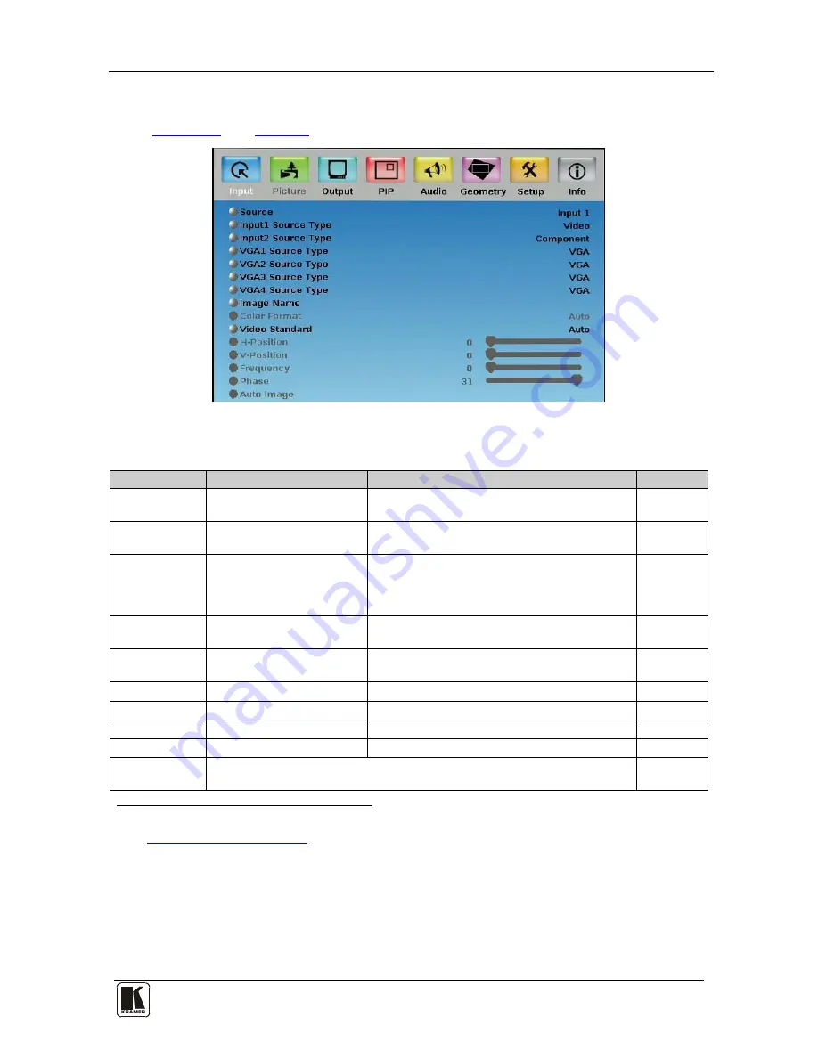
8.1 The Input Screen
Figure 13
and
Table 5
define the Input screen.
Figure 13: Input Screen
Table 5: Input Screen Functions
1
Setting
Function
Selection
Default
Source
2
Select the source
3
Input 1, Input 2, VGA 1, VGA 2, VGA 3, VGA 4,
HDMI 1, HDMI 2 or USB
Input (1 to 4)
Source Type
Select the source type
Component, YC or video (CV)
Video
Image Name
Shows the file name
4
of the
image displayed when the
USB port is selected as an
input
Color Format
Select the color format for
the HDMI inputs
Auto, RGB or YUV
Auto
Video Standard Select the video standard
Auto, NTSC, PAL, PAL-M, PAL-N, NTSC 4.43,
SECAM or PAL-60
Auto
H-Position
Set the horizontal position
5
Set according to the input resolution
V-Position
Set the vertical position
Set according to the input resolution
Frequency
Adjust the frequency
6
0 to 50
0
Phase
Adjust the phase
0 to 31
0
Auto image
Assesses the image and improves the quality accordingly, by automatically
adjusting the phase, frequency and position
1 Values may change according to the firmware version (you can download the up-to-date firmware version from our Web
site at
http://www.kramerelectronics.com
)
2 When switching sources, the image fades through black
3 Automatically updated when pressing an input front panel button on the machine
4 Supports JPEG format only. The JPEG file should not exceed a resolution of 2048x1536. If the image file is not within the
definition, the machine displays the message: “Size Too Big”
5 For UXGA and component video inputs
6 For UXGA inputs


