background image

KRAMER:  SIMPLE CREATIVE TECHNOLOGY


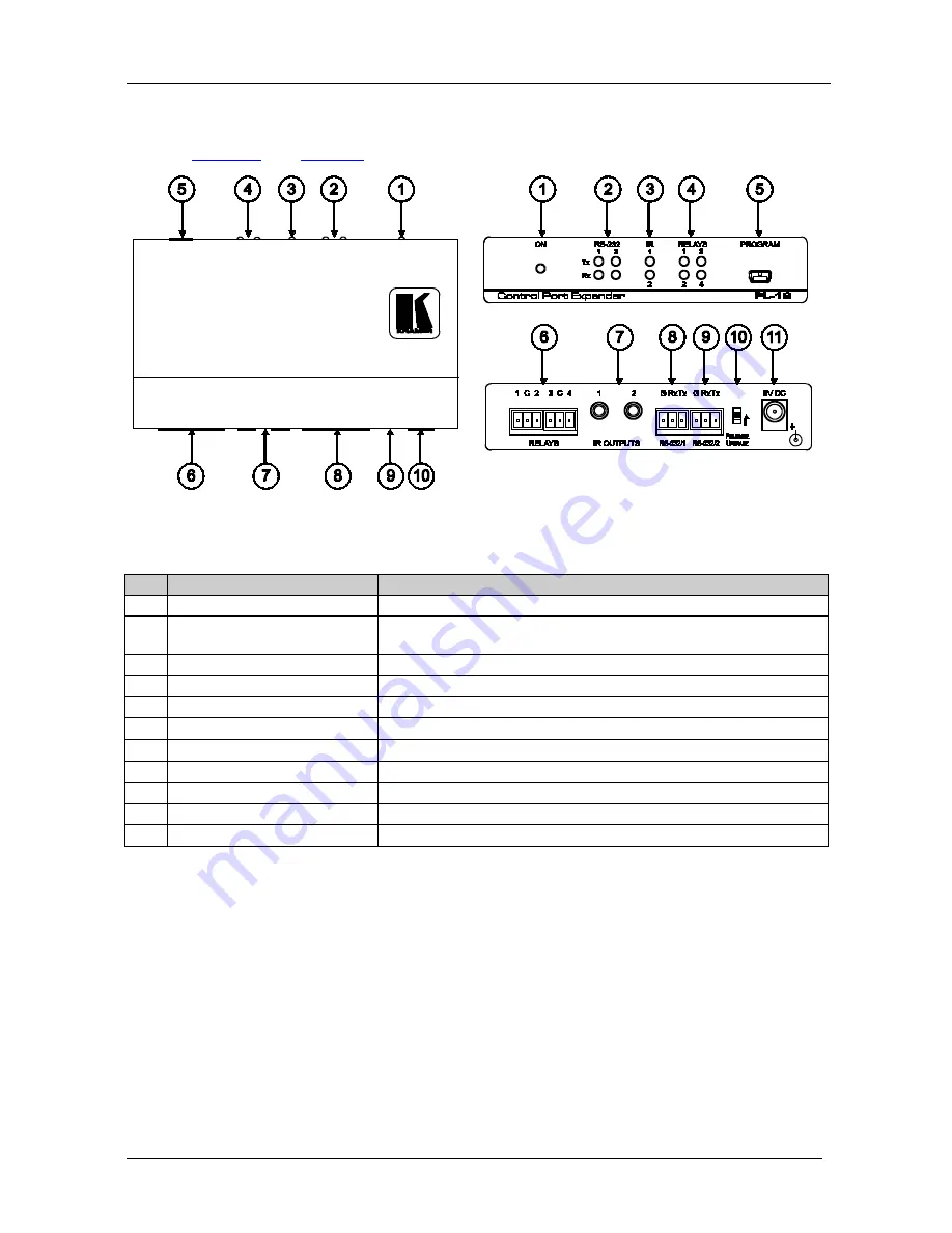
Your PL-18 Control Port Expander 


Your PL-18 Control Port Expander 

Figure 1

 and 

Table 1

 define 

PL-18


Figure 1: PL-18 Control Port Expander 

Table 1: PL-18 Control Port Expander Functions 

Feature 

Function 

ON

 LED 

Illuminates green when receiving power 

RS-232 Tx/Rx 

LEDs 

Illuminate red while transmitting and green while receiving data on 

an RS-232 port 

IR 

LEDs 

Illuminate green when an IR port is active 

RELAY 

LEDs 

Illuminate green when an relay is active (from 1 to 4) 

PROGRAM

 USB Connector 

Connects to a computer to upgrade firmware 

RELAY 

Terminal Blocks


Connect to relay-driven devices (from 1 to 4) 

IR OUTPUT 

3.5mm Mini Jacks


Connect to IR emitter cables (from 1 to 2) 

RS-232/1 

Terminal Block 

Connects to an RS-232 device that is controlled 

RS-232/2 

Terminal Block 

Connects to an external controller (PC, touch screen or RC device)  

10 

PROGRAM 

Switch 

For factory use only. Do not operate during firmware upgrade 

11 

5V DC 

+5V DC connector for powering the unit 


im Vertrieb von            CAMBOARD Electronics

www.camboard.de

Tel. 07131 911201
Fax 07131 911203

[email protected]

Содержание PL-18

Страница 1: ...Kramer Electronics Ltd USER MANUAL Model PL 18 Control Port Expander im Vertrieb von CAMBOARD Electronics www camboard de Tel 07131 911201 Fax 07131 911203 ce info camboard de...

Страница 2: ...9 Protocol 3000 Syntax 10 9 1 RS 232 2 Settings 10 9 2 Host Message Format 10 9 2 1 Simple Command 10 9 2 2 Command String 10 9 3 Device Message Format 11 9 3 1 Device Long Response 11 9 4 COMMAND TER...

Страница 3: ...or Message 15 Figure 6 Device Selection 16 Figure 7 Open File Window 17 Figure 8 Device and File Selected 18 Figure 9 Warning Window 18 Figure 10 Load Progress 19 Figure 11 Completion Message 19 Table...

Страница 4: ...r RC SV Configuration software Power adapter 5V DC input This user manual2 2 Getting Started We recommend that you Unpack the equipment carefully and save the original box and packaging materials for...

Страница 5: ...TECHNOLOGY Getting Started 2 2 1 Quick Start This quick start chart summarizes the basic setup and operation steps im Vertrieb von CAMBOARD Electronics www camboard de Tel 07131 911201 Fax 07131 9112...

Страница 6: ...er or an RC series device on RS 232 2 Four relays for the simplified and centralized control of room functions such as lighting closing blinds screen settings and so on Two IR output ports for IR cont...

Страница 7: ...Illuminate green when an relay is active from 1 to 4 5 PROGRAM USB Connector Connects to a computer to upgrade firmware 6 RELAY Terminal Blocks Connect to relay driven devices from 1 to 4 7 IR OUTPUT...

Страница 8: ...Connect RELAYS 3 and 4 to a screen 3 Connect the IR OUTPUTS as follows Connect IR OUTPUT 1 to a DVD Connect IR OUTPUT 2 to a display Figure 2 Connecting the PL 18 Control Port Expander 1 Switch OFF th...

Страница 9: ...chnical Specifications The PL 18 technical specifications are shown in Table 2 Table 2 PL 18 Control Port Expander Technical Specifications 3 PORTS 2 bi directional RS 232 ports on terminal block conn...

Страница 10: ...TYPE PORT_NUM CFG_VAL1 CFG_VAL2 CFG_VAL3 CFG_VAL4 CFG_VAL5 CFG_VAL6 CFG_VAL7 CFG_VAL8 RESULT CFG_VAL1 CFG_VAL2 CFG_VAL3 CFG_VAL4 CFG_VAL5 CFG_VAL6 CFG_VAL7 CFG_VAL8 PORT_TYPE UART ETH IR PORT_NUM IR 1...

Страница 11: ...cenario A specific binary port controls one specific external device e g one RC button opens a projector another RC button closes it using the same serial binary port The port is configured only once...

Страница 12: ...ARAMETERS OK Protocol Errors Syntax error ERR001 Command not available for this device ERR002 Parameter is out of range ERR003 Unauthorized access command run without the matching login ERR004 8 4 14B...

Страница 13: ...ller or a PC touch screen other serial controller 9 1 RS 232 2 Settings Port RS 232 2 Baud Rate 115 200 Data Bits 8 Stop Bits 1 Parity None Command Format ASCII 9 2 Host Message Format Start Address o...

Страница 14: ...e special characters for specific commands Parameters are separated by commas Message string Every command entered as part of a message string begins with a message starting character and ends with a...

Страница 15: ...coding such as X Refer to the controller manual 9 6 Command Forms Some commands have short name syntax in addition to long name syntax to allow faster typing The response is always in long syntax 9 7...

Страница 16: ...he latest firmware file3 1 Go to the Kramer Web site at from the Internet www kramerelectronics com 2 Navigate to SUPPORT Software Firmware Updates 3 Click on the link of the firmware that applies to...

Страница 17: ...the Connect button The Connect Window appears Note The PL 18 does not have an Ethernet interface Do not select any of the Ethernet options on the Connect window 1 You can download and install the late...

Страница 18: ...te If you try to connect to a device and it does not respond the following error message appears Click OK Verify that the device is powered on the cable connection is good and that you are trying to c...

Страница 19: ...ote In the Device Properties section you can update any of the active fields that have a white background After making any changes click Set Figure 6 Device Selection 5 In the device list box click to...

Страница 20: ...firmware file for example C Program Files Kramer Flash 8 Select the firmware file you downloaded in section 10 1 1 and click Open The firmware file appears in the Firmware file box im Vertrieb von CA...

Страница 21: ...cted 9 Click the Start Upgrade button to begin the file transfer The Warning window appears Figure 9 Warning Window 10 Click Yes to continue Load Progress appears in the bottom box im Vertrieb von CAM...

Страница 22: ...finished the completion message appears Figure 11 Completion Message 12 Click Close to close the P3K Wizard and remove the cable that connects the PL 18 to the PC im Vertrieb von CAMBOARD Electronics...

Страница 23: ...ard The P3K Wizard screen appears see Figure 3 3 Click the Connect button to open the Connect window see Figure 4 4 Choose the SERIAL USB connection and click OK The Connect window disappears and the...

Страница 24: ...ollowinstructions supplied with theproduct iii Repairorattemptedrepairby anyonenot authorized byKramer iv Anyshipment oftheproduct claims must bepresentedtothe carrier v Removalorinstallationoftheprod...

Страница 25: ...of Kramer distributors visit our Web site www kramerelectronics com where updates to this user manual may be found We welcome your questions comments and feedback Caution Safety Warning Disconnect the...

Отзывы: