5
PL-015B/f.
5
PL-015B/f.
Installation work
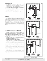
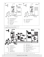
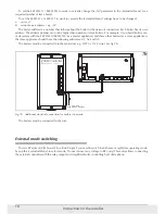
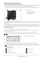
1. Hang the boiler up in a vertical position on fixing screws
with inlet and outlet pipes to the bottom, maintaining
clearances from the walls and the ceiling (see fig.1).
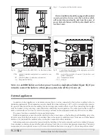
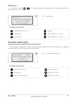
2. Connect the boiler to a central heating system equipped
with cut-off valves (see fig.2 & fig.3).
3. Fill the central heating system with a treated water, that
extends the life of the heating elements.
4. Vent the central heating system.
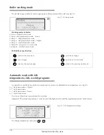
5. Connect a boiler to the electrical system (see fig. 4).
Instruction for the installer
1b
1a
Fig.1a, 1b, 1c Fixing the boiler to the wall
Important
The control panel allows for its co-operation in different
central heating systems, however the control panel needs
to be set accurately (see
„
Front control Panel
”
„
Extanded
Menu
”
). e.g. if the boiler only co-operates with an under-
floor heating system, a Tcomax (max. temperature in the
central heating system) must be set at 60°C and WCHG
(radiator coefficient) at
„
Pod
”
(see
„
Extended Menu
”
on
page 24).
1c
Special start-up procedure for EKCO.TM
A flow rate reading error may occur if you start-up the
unit at low ambient temperature. This error may occur
because the physical properties of antifreeze solution.
Under this circumstances, the special start-up procedure
will start if you:
-
activate the central heating or cylinder heating mode using
the control panel display (see fig.14),
-
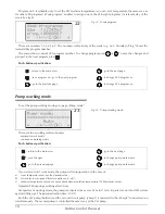
close the NA entry on ZIO board (see fig.6),
-
notice the
„
!
”
(an exclamation mark) at main view panel
display (see
„
Failures
”
page 12).
As a result, the medium will be warmed up to tempera-
ture that enabled you to read the flow rate correctly. The
duration of procedure depends on both the installation
capacity and the temperature inside the system.
When the main view panel display (fig.10, 11) and the
central heating parameters view (fig. 31) shows boiler
power value and (
„
-
”
,
„
--
”
) alter-nately it means that the
procedure is started.
The procedure will switch off automatically and the
unit will start normal operation once the minimal flow
rate is reached.
EKCO.M1z
EKCO.M1Nz
EKCO.TM
inlet
outlet
inlet
outlet
inlet
outlet


